


24
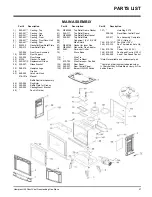
Hampton H25 Direct Vent Freestanding Gas Stove
CONVERTING A CLASS-
A METAL CHIMNEY OR
MASONRY CHIMNEY
TO A DIRECT VENT
SYSTEM
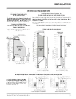
There are two different types of direct vent
conversion systems listed below. Follow the
appropriate directions for your installation.
A) Through an existing factory built metal chim-
ney going through the ceiling: A typical
conversion of this type is shown in diagram
1. The concept of direct vent conversion is
to connect an adaptor to an Underwriters
Laboratories (UL) listed 4 inch diameter
aluminum flex pipe which is then passed
down through the center of the existing
metal chimney system. Three sizes of Top
Adaptors are available from Simpson Dura-
Vent. The Retro Connector (909B) is at-
tached to the bottom of the flex pipe. The Top
Adaptor and the Retro Connector are at-
tached to the existing chimney with sheet
metal screws. The appliance is then con-
nected to the chimney with appropriate
black direct vent pipe and an adjustable
length section.
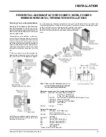
B) Through the wall of an existing masonry
chimney: A typical conversion of an exist-
ing masonry chimney is shown in Diagram
6. A Top Adaptor (985K) and Flashing are
used at the top of the masonry chimney. The
4 inch aluminum liner is connected to the
adaptor and is passed down the chimney
and out through the masonry wall and
attached to the Retro Connector (909B).
The Retro Connector is attached to the
masonry wall and then connected to the
direct vent pipe leading to the appliance.
Prior to installation and connection of the
vent system to a factory-built or masonry
chimney, the chimney must be inspected
and thoroughly cleaned by a qualified
service person, such as a certified chim-
ney sweep or home inspection service.
The direct vent system must not be con-
nected to a damaged factory-built or ma-
sonry chimney.
For factory built, zero clearance, and ma-
sonry chimneys cleanout doors and caps
or plugs for cleanout tee fittings and ash
dumps shall be secured in place and
sealed before installing a Direct Vent sys-
tem within the chimney.
If the appliance shuts off during opera-
tion, contact a qualified service person to
determine if a negative pressure and/or
leaky chimney condition exists. Do not
operate the appliance until the problem is
corrected.
Approved for US Installations Only
The use of an existing chimney as an air
intake is not covered under the ANSI
Z21.88b-1999, CSA 2.33b-M99 test meth-
ods and the resulting ITS/WHI product
certification. The code Authority Having
Jurisdiction must be consulted prior to
proceeding with this installation method.
Converting a Factory Built Metal
Chimney
1) Remove the existing chimney cap.
2) Measure the distance from the top end of
the chimney to the bottom of the ceiling
support box, add 3" (76mm) to this meas-
urement, and cut a section of the 4" flex
pipe to that length (the flex should already
be extended to its nominal length).
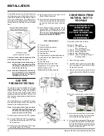
4) Pass the flex pipe down through the center
of the chimney system, and center the
adaptor on the top of the chimney pipe. Drill
four 1/8" diameter holes through the adap-
tor and into the chimney top. Insure that you
are in fact, drilling into the metal on the
chimney. Twist-lock the Termination Cap
(Part# 980 or 991) onto the Adaptor. (Dia-
gram 3 and 4).
Diagram 1
Diagram 2
Diagram 3
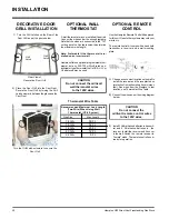
5) Pull the flex pipe down through the ceiling
support box, until it protrudes approximate-
ly 3" (76mm). Connect the flex pipe to the
Retro Connector by slipping it into the
4-3/4" diameter sleeve on the top side of the
Connector. Use 3 sheet metal screws to
assemble these two parts.
6) Push the flex pipe back up into the ceiling
support box, center the Retro Connector,
and attach it to the support box, or decora-
tive sleeve for double wall solid packed
pipe, with the sheet metal screws (sup-
plied). The holes in the Retro Connector are
pre-punched. Diagram 5.
Diagram 4
Diagram 5
3) Connect the end of the flex pipe section to
the underside of the Top Adaptor using 3
sheet metal screws. Diagram 2.
7) The connection between the appliance
and the Retro Connector may be completed
with sections of black direct vent pipe,
together with an adjustable length.
INSTALLATION


