


Hampton H25 Direct Vent Freestanding Gas Stove
21
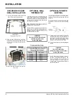
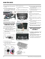
INSTALLATION
DURA-VENT VENTING
COMPONENTS
The Simpson Dura-Vent Direct Vent System
offers a complete line of component parts for
installation of both horizontal and vertical instal-
lation. Many items are offered in decorative
black, as well as galvanized finish. The galva-
nized pipe and fittings are used for concealed
locations such as attics or where corrosion is
a factor, such as above the roof line. Decora-
tive brass trim kits are available for both wall
thimbles and ceiling support boxes.
Part #
Description
971
Horiz. Termination Kit includes: 90
o
black
elbow, wall thimble cover, horiz. square
termination cap, 24" black pipe, 11" -14"
5/8" adjustable black pipe
970
Basic Horiz. Termination Kit includes:
90
o
black elbow, wall thimble cover,
horiz. square term. cap
978
Vert. Termination Kit includes 0/12 - 6/
12 pitch adjustable flashing, storm col-
lar, low profile term. cap
908B
6" Pipe Length-Black
907B
9" Pipe Length-Black
906
12" Pipe Length Galv.
906B
12" Pipe Length-Black
904
24" Pipe Length Galv.
904B
24" Pipe Length-Black
903
36" Pipe Length Galv.
903B
36" Pipe Length-Black
902
48" Pipe Length Galv.
902B
48" Pipe Length-Black
911B
11"-14 5/8" Adj. Pipe Length-Black
917B
17"- 24" Adj. Pipe Length Black
945
45
O
Elbow Galv.
945B
45
O
Elbow-Black
945G 45
O
Elbow-Swivel Galv.
945BG 45
O
Elbow-Swivel-Black
990
90
O
Elbow Galv.
990B
90
O
Elbow-Black
990G 90
O
Elbow-Swivel Galv.
990BG 90
O
Elbow-Swivel-Black
991
High Wind Term. Cap (Vertical)
980
Vertical Term. Cap
984
Horiz. Sq. Term. Cap
985
Horiz. Sq. High Wind Termination
Cap
982
Snorkel-14" Rise Term.Cap
981
Snorkel-36" Rise Term.Cap
940
Wall Thimble-Support/Box
941
Cathedral/Ceiling-Support/Box
3951
Brass Trim-WallThimble/Ceiling Support
963
Firestop Spacer
943
Flashing 0/12-6/12
943S
Flashing 7/12-12/12
953
Storm Collar
950
Vinyl Siding Standoff
988
Wall Strap
942
Wall Thimble
Parts not supplied by Dura-Vent
946-506/P Vent Guard (Optional)
640-530
Riser Vent Terminal (Optional)
948-128
Vinyl Siding Shield for Riser
Vent Terminal
946-228
Horizontal Square Termination Cap
You will require the following components with
your new Direct Vent Freestanding Gas Stove.
Please review your product to make sure you
have everything you need. In the event that you
are missing any part, contact your dealer.
Note: These are the minimum pieces
required. Other parts may be re-
quired for your particular installa-
tion. See above for a list of vent
parts.
If installing termination on a siding covered wall,
a vinyl siding standoff or furring strips can be
used in order to ensure that the termination is
not recessed into siding.
The vinyl siding standoff is required for walls
with vinyl siding.
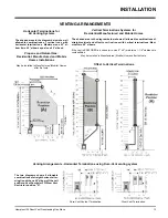
Minimum components for a Dura-Vent
Horizontal Installation:
A) Dura-Vent Horizontal Termination Kit
B) Wall Thimble (required for combustible
walls)
Minimum components for a Dura-Vent
Vertical Termination:
D) Dura-Vent Vertical Termination Kit. See
above for pipe lengths.
Diagram 2a
HORIZONTAL
INSTALLATIONS
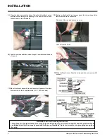
1)
Set the unit in its desired location. Check to
determine if wall studs are in the way when
the venting system is attached. If this is the
case, you may want to adjust the location
of the unit.
2)
Assemble the desired combination of pipe
and elbow to the appliance adapter with
pipe seams oriented down. Offset the pipe
seams as double seams in one place will
cause the outer pipe to take an oval shape.
Kit comes complete with 18" of straight vent
- 6-5/8" dia. black outer pipe and 4" dia. inner
vent.
3)
With the pipe attached to the stove, slide the
stove into its correct location, and mark the
wall for a 9-1/2" (inside dimensions) round
hole. The center of the round hole should
line up with the centerline of the horizontal
pipe, as shown in diagram 1. Cut and frame
the 9-1/2 round hole in the exterior wall
where the vent will be terminated. If the wall
being penetrated is constructed of non-
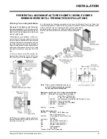
Note:
a)
The horizontal run of vent should have a
1/4 inch rise for every 1 foot of run towards
the termination. Never allow the vent to run
downward. This could cause high temper-
atures and may present the possibility of a
fire.
b)
The location of the horizontal vent termina-
tion on an exterior wall must meet all local
and national building codes, and must not be
blocked or obstructed. For External Vent
Terminal Locations, see diagram on page 9.
c) Snorkel Terminations:
For installations requiring a vertical rise on
the exterior of the building, 14-inch and 36-
inch tall Snorkel Terminations as shown in
Dia. 2 are available, as well as the standard
Riser Vent. Follow the same installation
procedures as used for standard Horizon-
tal Termination. NEVER install the snorkel
upside down.
Diagram 1
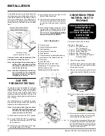
*Dia 2a & 2b: As specified
in CGA B149 Installation
Code. Local codes or reg-
ulations may require dif-
ferent clearances.
combustible material, i.e. masonry block or
concrete, a 7" diameter hole is acceptable.
Diagram 2b


