


24
Subject to change without notice
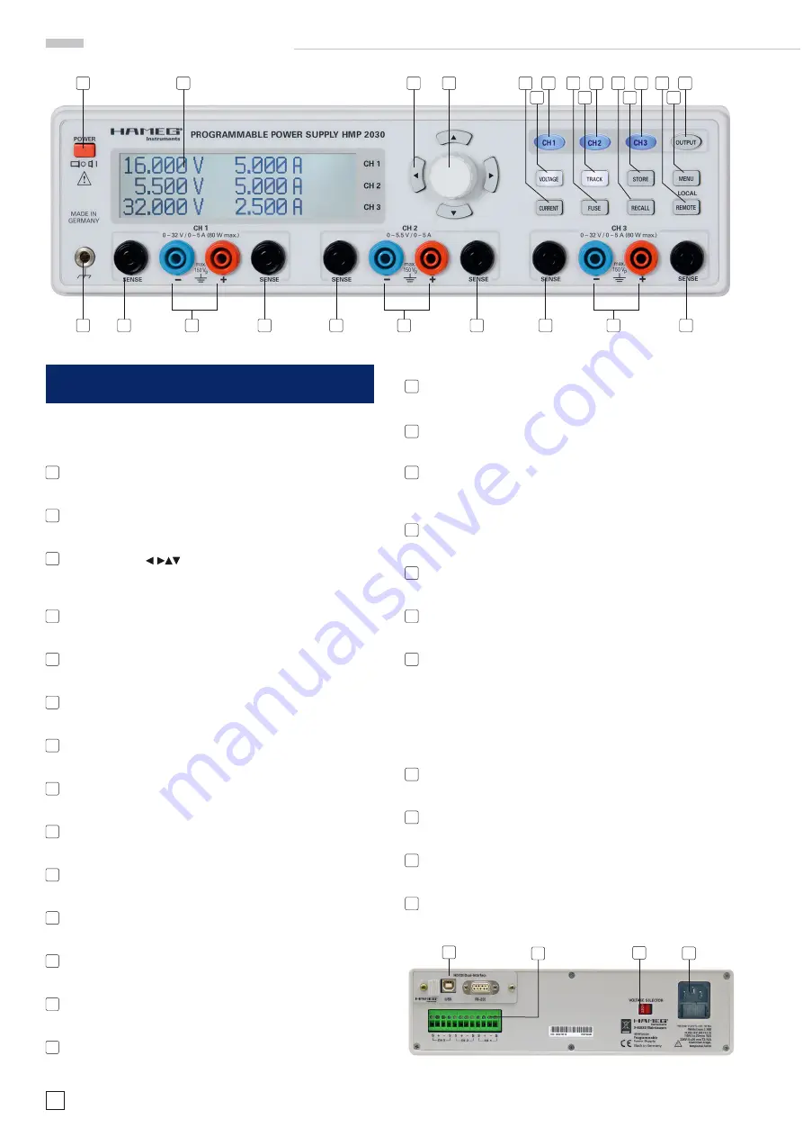
O p e r a t i n g c o n t r o l s
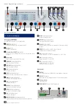
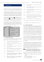
2 Controls and display
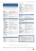
Front panel HMP2030
(for HMP2020 channel 3 is not applicable)
1
POWER
(pushbutton)
Power switch turns the instrument on/off
2
Display
(LCD)
Display of parameters
3
Arrow buttons
(illuminated)
Cursor keys for shifting the cursor to the position to be
changed
4
Rotary knob
Knob to adjust and activate the values
5
CURRENT
(illuminated button)
Adusting current settings
6
VOLTAGE
(illuminated button)
Adusting output voltage
7
CH1
(illuminated button)
Activates channel 1
8
FUSE
(illuminated button)
Elektronic fuse, selectable for each channel
9
TRACK
(illuminated button)
Activates the Tracking Function
10
CH2
(illuminated button)
Activates channel 2
11
RECALL
(illuminated button)
Restore of instrument settings
12
STORE
(illuminated button)
Storing of instrument settings
13
CH3
(Taste beleuchtet)
Activates channel 3
14
REMOTE / LOCAL
(illuminated button)
Toggling between front panel and external operation
15
MENU
(illuminated button)
Display of menu options
16
OUTPUT
(illuminated button)
Turn on/off selected channels
17
Ground
(4 mm socket)
Ground connector (directly connected to the mains safety
ground)
18
SENSE
(4 mm safety sockets; 2 per channel)
Compensation of lead resistances
19
CH1
(4 mm safety sockets)
Output channel 1; 0...32V / 5A (HMP2020 0...32V / 10A)
20
CH2
(4 mm safety sockets)
Output channel 2; 0...5,5V / 5A
21
CH3
(4 mm safety sockets)
Output channel 3; 0...32V / 5A
(HMP2020 without channel 3)
Rear panel
22
Interface
HO720 Dual Interface USB/RS-232 is provided as standard
23
OUTPUT
(connector)
Rear outlets for easy integration into 19” rack mount systems
24
Voltage selector
115V resp. 230V
25
POWER INPUT
(Power Cord Receptacle)
22
23
24
25
2
4
5
6
7
8
9
10
11
12
13
14
15
16
18
1
17
19
18
18
20
18
18
21
18
3
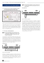
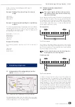
Fig. 2.1: Frontpanel HMP2030
Fig. 2.2: Rear panel HMP2020 / HMP2030


