background image

25

Subject to change without notice

          O p e r a t i o n   o f   t h e   H M P 2 0 2 0   /   H M P 2 0 3 0

3  Short description HMP2020 / HMP2030

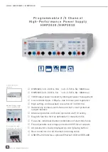
The programmable 2 resp. 3 channel high-performance po-
wer supplies HMP2020 / HMP2030 are based on the classical 
transformer principle, utilising a high effi ciency electronic pre-
regulator and a secondary linear voltage regulator. This design 
concept stands for high output power, a compact sized housing 
and high effi ciency, combined with smallest  residual ripple.

According to the type of instrument there are up to 3 channels, 
each electrically insulated and combinable. The HMP2030 has 
two identical channels (CH1 

19

 and CH3 

21

) with a voltage range 

of 0 to 32 V. Due to the intelligent  power management, 5 A can be 
drawn at 16 V and 2.5 A are delivered at the full rated output voltage 
of 32 V. The second channel delivers 0 to 5.5 V at 5 A. Both instru-
ments (HMP2020/ HMP2030) can likewise provide an output power 
of 188 W. But besides the 5.5 V channel there is also one more 32 V 
channel doubling its maximum current to 10 amps.

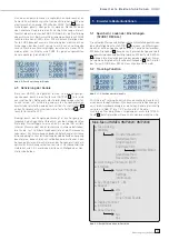
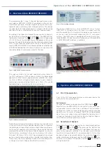
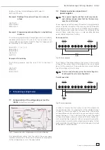
Fig. 3.1: HMP2020 (2 channel version)

The high resolution for set and read back values down to 
1 mV/0.1 mA makes HMP an ideal solution for demanding 
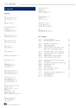
applications. What’s more, applying the  EasyArb function, users 
can form arbitrary voltage/current shapes to each channel, 
mastering a minimum timing step down to 10 ms. This can be 
realized as well as remote control or local control.

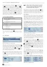
Fig. 3.2:  Arbitrary voltage step

Due to their electrically insulated, earth free, overload and short 
circuit proof outputs, they can be operated in series or in parallel 
to deliver high voltage or high current output. A basic prerequisi-
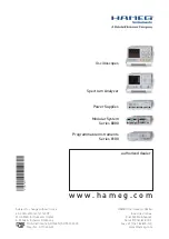
te is the use of separate electronic fuses, which can be logically 
combined ( FuseLink) to shut down linked channels in case of a 
fault condition, according to the user’s setup (e.g. CH1 follows 
CH2 and CH3 follows CH1 or CH2). Special emphasis has been 
put on a comfortable and practice oriented tracking function. 
If necessary, the corresponding channels are selected prior to 
a voltage or current change and altered in common 

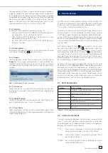
Fig. 3.3: Fuse Linking aktivated 

The series HMP has a 2-lines (HMP2020) resp. 3-lines 
(HMP2030) LCD-Display (240 x 64 Pixel). A compact unit size 
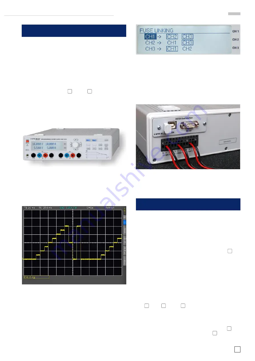
and the availability of all outputs (including sense terminals) 
on the rear side facilitate the integration into 19”  rack mount 
systems. The HMP series is equipped with a electrically insu-
lated USB/RS-232 dual interface. Optionally, an Ethernet/USB 
or GPIB (IEEE-488) interface is available.


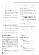
Fig. 3.4: Outputs on the rear side enables the integration into 19”  rack mount 
systems

4  Operation of the HMP2020 / HMP2030

4.1  First time operation

Prior to the fi rst time operation please note and observe the 
safety instructions given above!

Switching on

Turn the instrument on by pushing the POWER button 

1

.

After turn-on the HMP2020/2030 will restart in the same ope-
rating mode it was in when it was switched off. All instrument 
settings are stored in a nonvolatile memory and are recalled 
upon turn-on. As a rule, all outputs (OUTPUT) will be disabled 
upon turn-on in order to prevent inadvertent application of 
voltage to a load which might destroy it by too high a voltage or 
current due to settings previously stored. 

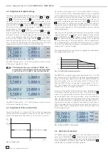
4.2  Selection of channels

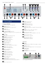
Select the channels by pressing the associated pushbuttons 
CH1 

7

, CH 2 

10

 or CH3 

13

. After pressing the buttons the 

channel LEDs will light up green. All subsequent settings will 
refer to the channels selected. If no channels were selected 
the LEDs will remain dark. It is recommended to fi rst set the 
desired voltages and currents before the outputs will be acti-
vated simultaneously by pressing the OUTPUT button 

16

. (see 

Activation of channels) If the button OUTPUT 

10

 is activated it 

will light up white.

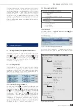
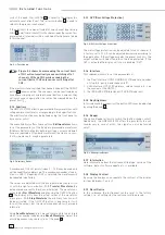
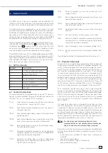
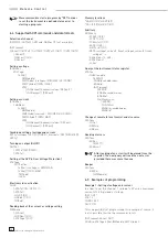
Summary of Contents for HMP2020

Page 1: ...P o w e r s u p p l y H M P 2 0 2 0 H M P 2 0 3 0 Handbuch Manual Deutsch English ...

Page 2: ...en der Anzeige und Messwerte über die vorgegebenen Spezifikationen hinaus können durch die äußeren Umstände in Einzelfällen jedoch auftreten HAMEG Instruments GmbH A l l g e m e i n e H i n w e i s e z u r C E K e n n z e i c h n u n g KONFORMITÄTSERKLÄRUNG DECLARATION OF CONFORMITY DECLARATION DE CONFORMITE DECLARACIÓN DE CONFORMIDAD Hersteller Manufacturer Fabricant Fabricante HAMEG Instruments ...

Page 3: ...etriebnahme des Gerätes 9 4 2 Auswählen der Kanäle 10 4 3 Einstellen der Ausgangsspannung 10 4 4 Einstellen der Strombegrenzung 10 4 5 Aktivierung der Kanäle 11 5 Erweiterte Bedienfunktionen 11 5 1 Speichern Laden der Einstellungen 11 STORE RECALL 11 5 2 Tracking Funktion 11 5 3 Menü Optionen MENU 12 6 Remote Betrieb 13 6 1 SCPI Kommandos 13 6 2 Common Commands 13 6 3 Program Commands 14 6 4 Unter...

Page 4: ...e erdfreie und kurzschlussfeste Ausgänge Komfortabler Parallel und Serienbetrieb durch U I Tracking EasyArb Funktion für frei definierbare U I Verläufe FuseLink individuell verknüpfbare elektronische Sicherungen Frei einstellbarer Überspannungsschutz OVP für alle Ausgänge Klare Darstellung aller Parameter über LCD und Tastenbeleuchtung Rückseitige Anschlüsse für alle Kanäle einschließlich Sense US...

Page 5: ...mA at I 500mA Messgenauigkeit Spannung 0 05 2mV Strom 500mA 0 05 0 5mA typ 0 2mA 500mA 0 05 2mA typ 1mA Restwelligkeit 3Hz 100kHz 3Hz 20MHz Spannung 150μVeff 1 5mVeff typ Strom 1mAeff Stabilisierung bei Last änderung 10 90 Spannung 0 01 2mV Strom 0 01 250μA Stabilisierung bei Netz spannungsänderung 10 Spannung 0 01 2mV Strom 0 01 250μA Vollständige Lastausregelung bei 10 90 Lastsprung 100μs Ausreg...

Page 6: ... mungen für elektrische Mess Steuer Regel und Laborge räte gebaut geprüft und hat das Werk in sicherheitstechnisch einwandfreiem Zustand verlassen Es entspricht damit auch den Bestimmungen der europäischen Norm EN 61010 1 bzw der internationalen Norm IEC 61010 1 Um diesen Zustand zu erhalten und einen gefahrlosen Betrieb sicherzustellen muss der Anwender die Hinweise und Warnvermerke in dieser Bed...

Page 7: ...end der Lagerung oder des Transportes darf die Umgebungstemperatur zwischen 20 C und 70 C betragen Hat sich während des Transportes oder der Lagerung Kondenswasser gebildet muss das Gerät ca 2 Stunden akklimatisiert und durch geeignete Zirkulation ge trocknet werden Danach ist der Betrieb erlaubt Das Gerät darf aus Sicherheitsgründen nur an vorschriftsmä ßigen Schutzkontaktsteckdosen oder an Schut...

Page 8: ...L Taste beleuchtet Umschalten zwischen Tastenfeld und externer Ansteue rung B e z e i c h n u n g d e r B e d i e n e l e m e n t e 15 MENU Taste beleuchtet Aufrufen der Menüoptionen 16 OUTPUT Taste beleuchtet Ausgewählte Kanäle ein bzw ausschaltbar 17 Massebuchse 4mm Buchse Bezugspotentialanschluss mit Schutzleiter verbunden 18 SENSE 4mm Sicherheitsbuchsen 2 x pro Kanal Kompensation der Zuleitung...

Page 9: ...ch mit 2 5A belastet werden können Auf Kanal 2 werden 0 bis 5 5V mit 5A bereitgestellt Wie das HMP2030 liefert das HMP2020 eine Leistung von 188W jedoch steht hier neben dem 5 5V Kanal zu Gunsten des doppelten Ausgangsstromes von bis zu 10A nur ein 32V Kanal zur Verfügung Abb 3 1 HMP2020 2 Kanal Version Die hohe Einstell und Rückleseauflösung von bis zu 1mV 0 1mA ist für Anwendungen mit höchsten An...

Page 10: ...etzt werden 10 000V Abb 4 2 Einstellbare Maximalwerte HMP2020 Beim HMP2020 stellt CH1 durchgehend 0 32V bereit wobei der Ausgangsstrom der Leistungshyperbel folgt vergl Abb 4 4 4 4 Einstellen der Strombegrenzung Strombegrenzung bedeutet dass nur ein bestimmter maxima ler Strom Imax fließen kann Dieser wird vor der Inbetriebnahme einer Versuchsschaltung am Netzgerät eingestellt Damit soll verhindert...

Page 11: ...r Ausgleichströme bitte unbedingt vor Lastanschaltung den betreffenden Ausgang deaktivieren danach die Last verbinden und erst danach den Ausgang aktivieren Beim Aktivieren des Ausgangs wird so ein optimales Einschwingverhalten realisiert Hochempfindliche Halbleiter wie z B Laserdioden bitte nach Maßgabe des Her stellers betreiben 5 Erweiterte Bedienfunktionen 5 1 Speichern Laden der Einstellungen ...

Page 12: ...saktiv DieAusgängekönnenjederzeitwiedermitderent sprechendenKanalwahltasteaktiviertwerden wobeidieseimFalle bleibenden Überstomes sofort wieder abgeschaltet werden 5 3 2 Arbitrary Mit dem HMP2020 bzw HMP2030 können frei programmierbare Signalformen erzeugt und innerhalb der vom Gerät vorgegeben Grenzwerte für Spannung und Strom des jeweiligen Kanals wiedergegeben werden Die Arbitrary Funktion kann...

Page 13: ...tp www hameg com Um eine erste Kommunikation herzustellen benötigen Sie ein serielles Kabel 1 1 und ein beliebiges Terminal Programm wie z B Windows HyperTerminal das bei jedem Windows Betriebs system enthalten ist Eine detailierte Anleitung zur Herstellung der ersten Verbindung mittels Windows HyperTerminal finden sie in unserer Knowledge Base unter http www hameg com hyperterminal Die LED der Rem...

Page 14: ...en Angaben Elemente aus der Ebene ROOT Wurzel sind SCPI Kommandos können als Lang oder Kurzform gesendet werden Die Langform ist das volle Wort mit maximal 12 Zei chen Beispiel MEASure Die Kurzform besteht aus den ersten 4 Zeichen der Langform Beispiel MEAS Wenn jedoch das vierte Zeichen ein Vokal ist und die 4 Zeichen nicht die Langform bilden besteht die Kurzform nur aus den ersten 3 Zeichen z B...

Page 15: ...der Fehlerliste gelöscht Die nächste Abfra ge zeigt den nächsten Fehler an wenn ein weiterer Eintrag im Fehlerregister abgelegt wurde Beeper SYSTem BEEPer IMMediate 6 5 Programmierbeispiele Beispiel 1 Einstellen von Strom und Spannung Um am Kanal 1 eine Spannung von 2V und einen maximalen Strom von 0 5A einzustellen können Sie folgende Befehlsfolge eingeben INST OUT1 VOLT 2 CURR 0 500 OUTP ON Dies...

Page 16: ... addieren sich bei dieser Art der Verschaltung die einzelnen Ausgangsspannungen Es fließt durch alle Aus gänge derselbe Strom Die Strombegrenzungen der in Serie geschalteten Ausgänge sollten auf den gleichen Wert eingestellt sein Geht einer der Ausgänge in die Strombegrenzung bricht naturgmäß die Gesamtspannung ein Bei der Reihenschaltung ist darauf zu achten dass die zulässige Schutzkleinspannung ...

Page 17: ...Sicherungstypen 7 Sicherungswechsel 7 Signalgeräusche 13 Spannungsbereich 10 Spannungsregelung 10 Speicherplatz 11 Start Waveform 11 12 Stop Waveform 11 12 Strombegrenzung 10 11 12 Stützpunkte 12 Systemkommandos 13 Terminal Programm 13 Tracking Funktion 11 Tracking Modus 11 Transfer Waveform 11 12 Transport 6 Treiber 13 Überspannungsschutz 12 13 Umgebungstemperatur 7 Versuchsschaltung 10 VOLTAGE 8...

Page 18: ...ller Manufacturer Fabricant Fabricante HAMEG Instruments GmbH Industriestraße 6 D 63533 Mainhausen Die HAMEG Instruments GmbH bescheinigt die Konformität für das Produkt The HAMEG Instruments GmbH herewith declares conformity of the product HAMEG Instruments GmbH déclare la conformite du produit HAMEG Instruments GmbH certifica la conformidad para el producto Bezeichnung Product name Programmierba...

Page 19: ...MP2020 HMP2030 25 4 Operation of the HMP2020 HMP2030 25 4 1 First time operation 25 4 2 Selection of channels 25 4 3 Adjustment of output voltage 26 4 4 Adjustment of the current limits 26 4 5 Activation of channels 26 5 Extended functions 27 5 1 Storing recalling settings STORE RECALL 27 5 2 Tracking function 27 5 3 Menu options MENU 27 6 Remote Control 29 6 1 SCPI commands 29 6 2 Common Commands...

Page 20: ...Galvanically isolated earth free and short circuit protected output channels Advanced parallel and serial operation via V I tracking EasyArb function for free definable V I characteristics FuseLink individual channel combination of electronic fuses Free adjustable overvoltage protection OVP for all outputs All parameters clearly displayed via LCD glowing buttons Rear connectors for all channels in...

Page 21: ...rement connection in blue HZ13 Interface cable USB 1 8m HZ14 Interface cable serial 1 1 HZ42 2RU 19 Rackmount Kit HZ72 GPIB Cable 2m HM2020 2030E 091109 ce Subject to alterations HAMEG Instruments GmbH DQS certified in accordance with DIN EN ISO 9001 2000 Reg No DE 071040 QM HAMEG Instruments GmbH Industriestr 6 D 63533 Mainhausen Tel 49 0 6182 800 0 Fax 49 0 6182 800 100 www hameg com info hameg ...

Page 22: ...e European standard EN 61010 1 resp to the internatio nal standard IEC 61010 1 Please observe all warnings in this manual in order to preserve safety and guarantee operation without any danger to the operator According to safety class 1 requirements all parts of the housing and the chassis are con nected to the safety ground terminal of the power connector In case of doubt the power connector shou...

Page 23: ...urning an instrument to HAMEG ask for a RMA number either by internet http www hameg com or fax If you do not have an original shipping carton you may obtain one by calling the HAMEG service dept 49 0 6182 800 500 or by sending an email to service hameg com 1 10 Maintenance The instrument does not require any maintenance Dirt may be removed by a soft moist cloth if necessary adding a mild detergen...

Page 24: ... Storing of instrument settings 13 CH3 Taste beleuchtet Activates channel 3 14 REMOTE LOCAL illuminated button Toggling between front panel and external operation 15 MENU illuminated button Display of menu options 16 OUTPUT illuminated button Turn on off selected channels 17 Ground 4 mm socket Ground connector directly connected to the mains safety ground 18 SENSE 4 mm safety sockets 2 per channel...

Page 25: ...ault condition according to the user s setup e g CH1 follows CH2 and CH3 follows CH1 or CH2 Special emphasis has been put on a comfortable and practice oriented tracking function If necessary the corresponding channels are selected prior to a voltage or current change and altered in common Fig 3 3 Fuse Linking aktivated The series HMP has a 2 lines HMP2020 resp 3 lines HMP2030 LCD Display 240 x 64...

Page 26: ...ill hence decrease below the value set If a channel is activated by pressing the VOLTAGE 6 and OUTPUT 16 buttons and if its settings are changed the channel LED will change from green indicating voltage regulation to red indi cating current regulation if the adjustments cause a change of regulation mode After turn on the instrument will automatically enter the voltage regulation mode The maximum c...

Page 27: ... position of all three channels Press the TRACK button 9 to activate the tracking mode then the individual channels can be selected If e g after pres sing the VOLTAGE button 6 the voltage is adjusted with the knob 4 or the arrow buttons 3 the voltages of the selected channels are changed by the same amount The same applies to the currents if the CURRENT button 5 was pressed The HMP2020 2030 keeps ...

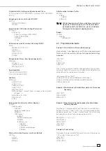
Page 28: ...button With Transfer Waveform the data entered are sent to the channel selected The waveform is activated by Start Waveform and pressing the OUTPUT button 16 The display will show the actual values of the waveform in progress With Stop Waveform the arbitrary function will be deactivated If the OUTPUT button is depressed it will turn off the output but the waveform generator will proceed internally...

Page 29: ... Command sets the service request enable register SRE Service Request Enable Query query of the service request enable register STB 1 Read Status Byte Query query of the status byte register TST 1 Self Test Query self test query error code WAI Wait to Continue Command command which halts the execution of a command string until preceding commands have been executed SAV x Save Command saves instrume...

Page 30: ...TRIPed Reading back of the current or voltage setting MEASure SCALar CURRent DC VOLTage DC Memory locations SAV 0 1 2 3 4 5 6 7 8 9 RCL 0 1 2 3 4 5 6 7 8 9 Arbitrary ARBitrary STARt 1 2 3 STOP 1 2 3 TRANsfer 1 2 3 SAVE 1 2 3 RESTore 1 2 3 DATA voltage1 current1 time1 voltage2 current2 time2 voltage3 REPetitions 0 255 REPetitions CLEar Query of the instrument status register STATus QUEStionable EVE...

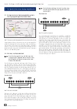
Page 31: ...series or parallel connection if they are expressly destined for such operation this is the case for all HAMEG power supplies Series resp parallel connection increases the voltage resp the current these connections are as a rule possible because power supply outputs are floating Series operation Fig 7 2 Series operation The voltages of the outputs add up the current is the same in all ouputs The cu...

Page 32: ...acking function 27 Transport 22 Types of fuses 23 V VOLTAGE 24 26 27 Voltage regulation 26 Voltage regulation mode 26 W Warranty 23 Windows HyperTerminal 29 List of figures Fig 2 1 Frontpanel HMP2030 24 Fig 2 2 Rear panel HMP2020 HMP2030 24 Fig 3 1 HMP2020 2 channel version 25 Fig 3 2 Arbitrary voltage step 25 Fig 3 3 Fuse Linking aktivated 25 Fig 3 4 Outputs on the rear side enables the inte grati...

Page 33: ...33 Subject to change without notice A p p e n d i x ...

Page 34: ...34 Subject to change without notice ...

Page 35: ...35 Subject to change without notice ...

Page 36: ... Instruments GmbH D 63533 Mainhausen A Rohde Schwarz Company Tel 49 0 61 82 800 0 DQS Certification DIN EN ISO 9001 2000 Fax 49 0 61 82 800 100 Reg Nr 071040 QM sales hameg com Oscilloscopes Spectrum Analyzer Power Supplies Modular System Series 8000 Programmable Instruments Series 8100 w w w h a m e g c o m 43 2030 2010 ...

Reviews: