28
Subject to change without notice
E x t e n d e d f u n c t i o n s
click of the knob. Press MENU
15
to revert to the display (no
automatic reset after 5 sec). The left arrow button
3
is used to
return to the previous menu level.
If the electronic fuse was activated for one channel by pressing
FUSE
8
and if the current of this channel exceeds the current I
max
preselected all channels will be switched off which were linked
to this channel.
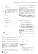
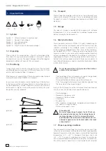
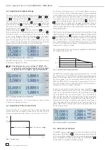
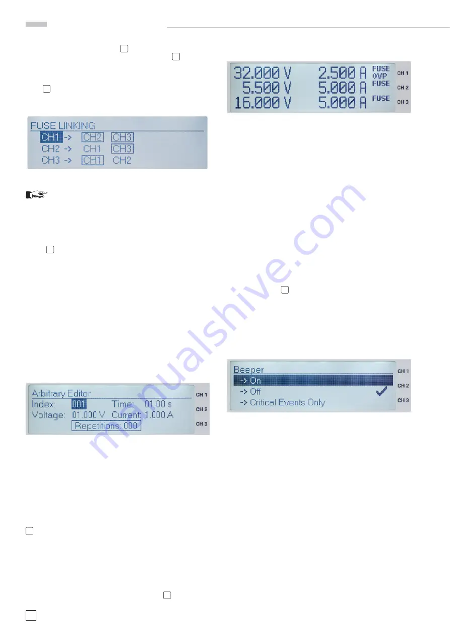
Fig. 5.6: Fuse Linking
Figure 5.6 shows how exceeding the current limit
of CH1 will automatically cause switching off of
channels CH2 and CH3 while exceeding the
current limit of CH2 only causes switching off of
CH3.
If the electronic fuse switched the channels linked off the OUPUT
button
16
remains active. The channels can be reactivated any
time by pressing the associated channel buttons, however, they
will only come on again after the current decreased below the
preset limit I
max
.
5.3.2 Arbitrary
The HMP 2020/2030 allow to generate arbitrary waveforms with
voltage and current levels corresponding to their specifi cations.
The arbitrary function may be defi ned using the front panel or
by remote control.
The menu Arbitrary offers these options:
Edit waveform
allows
to set the parameters of the freely programmable waveforms
( Arbitrary Editor). Set points defi ning voltage, current and dwell
time are required, all standard waveforms like staircase, saw-
tooth, sine wave etc. may be generated.
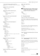
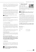
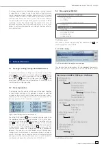
Fig. 5.7: Arbitrary Editor
A maximum of 128 set points (index 0 ... 128) may be used and
will be repetitively addressed. The maximum number of repe-
titions is 255. If “Repetitons 000” is selected, the waveform will
be repeated indefi nitely.
The values are adjusted with the knob, entered by center click
or with the right arrow button. With
Transfer Waveform
the
data entered are sent to the channel selected. The waveform is
activated by
Start Waveform
and pressing the OUTPUT button
16
. The display will show the actual values of the waveform
in progress. With
Stop Waveform
the arbitrary function will
be deactivated. If the OUTPUT button is depressed it will
turn off the output, but the waveform generator will proceed
internally.
Using
Save Waveform
up to 3 waveforms are able to be stored
which later maybe loaded using
Recall Waveform
. Select the
according memory by center click of the knob
4
.
5.3.3 OVP (Over Voltage Protection)
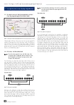
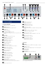
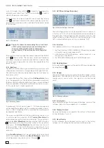
Fig. 5.8: OVP (Over Voltage Protection)
The overvoltage protection can be adjusted for each channel, it
is factory-set to 33 V; it can be adjusted downward according to
the application. If the voltage exceeds the preset limit V
max
, the
output will be switched off and thus the load protected. If the
OVP is activated the display will show a blinking “OVP”.
5.3.4 Interface
This submenu allows to set the parameters of:
1. the Dual Interface HO720 USB/RS-232 (Baud rate, number
of stop bits, parity, handshake on/off).
2. LAN Interface HO730 (IP address, sub net mask etc., see
the manual of the HO730 )
3. the IEEE-488 GPIB Interface HO740 (GPIB address).
5.3.5 Key Brightness
In this submenu the intensity of the button LEDs may be adjusted
by using the knob
4
.
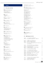
5.3.6 Beeper
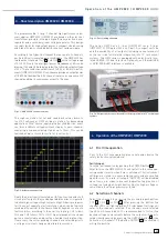
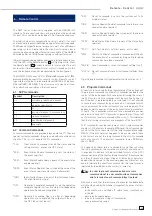
The option Beeper allows to switch the button sounds on/off.
Additionally, the HMP2020/2030 offers the possibility to emit
sounds only in case of error; this signal can also be turned
on/off.
Fig. 5.9: Menu option Beeper
5.3.7 Information
Here information about the instrument like type, version of the
software, date of software update etc. is available.
5.3.8 Display Contrast
By using the knob you can regulate the contrast of the display
in steps between –9 and +9.
5.3.9 Reset Device
In this submenu the instrument can be reset to the factory
settings, i.e. all settings by the customer will be erased.

