15
Subject to change without notice
In this example t = 3 cm and T = 10 cm, the phase difference in
degrees will result from:
5
3
ϕ
° = —
·
360° = —
·
360° = 108°
T
10
or in angular units:
t 3
arc
ϕ
° = —
·
2
π
= —
·
2
π
= 1,885 rad
T
10
Very small phase differences with moderately high frequencies
may yield better results with Lissajous fi gures.
However, in order to get higher precision it is possible to switch
to higher sensitivities – after accurately positioning at graticule
centre , thus overdriving the inputs resulting in sharper zero
crossings. Also, it is possible to use half a period over the full
10 cm. As the time base is quite accurate, increasing the time
base speed after adjusting for e.g. one period = 10 cm and
positioning the fi rst crossing on the fi rst graticule line will also
give better resolution.
Measurement of amplitude modulation
The momentary amplitude at time t of an hf carrier frequency
modulated by a sinusoidal low frequency is given by:
u = U
T
·
sin
Ω
t + 0,5 m
·
U
T
·
cos (
Ω
-
ω
) t - 0,5 m
·
U
T
·
cos (
Ω
-
ω
) t
where: U
T
= amplitude of the unmodulated carrier
Ω
=
2
π
F = angular carrier frequency
ω
=
2
π
f = modulation angular frequency
m
= modulation degree (
≤
1
v
100%)
In addition to the carrier a lower side band F – f and an upper
side band F + f will be generated by the modulation.
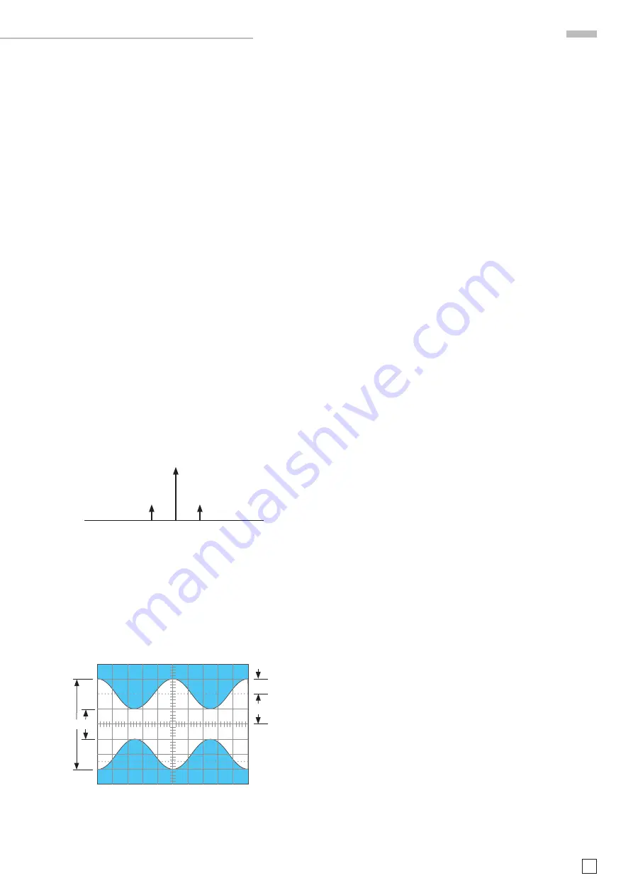
Picture 1: Amplitudes and frequencies with AM (m = 50 %) of
the spectra
As long as the frequencies involved remain within the scope’s
bandwidth the amplitude-modulated hf can be displayed. Pre-
ferably the time base is adjusted so that several signal periods
will be displayed. Triggering is best done from the modulation
frequency. Sometimes a stable displayed can be achieved by
twiddling with the time base variable.
Picture 2: Amplitude modulated hf. F = 1 MHz, f = 1 kHz,
m = 50 %, U
T
= 28,3 mV
rms
Set the scope controls as follows in order to display the picture
2 signal:
CH1 only, 20 mV/cm, AC
TIME/DIV: 0.2 ms/cm
Triggering: NORMAL, AC, internal.
Use the time base variable or external triggering.
Reading a and b off the screen the modulation degree will
result:
a – b
a – b
m = —— or m = ——
·
100 [%]
a + b
a + b
a = U
T
(1 + m) and b = U
T
(1 – m)
When measuring the modulation degree the amplitude and time
variables can be used without any infl uence on the result.
O p e r a t i n g m o d e s o f t h e v e r t i c a l a m p l i f i e r
F – f
F
F + f
0,5 m · U
T
0,5 m · U
T
U
T
b
a
m · U
T
U
T
Test Equipment Depot - 800.517.8431 - 99 Washington Street Melrose, MA 02176
FAX 781.665.0780 - TestEquipmentDepot.com


