background image

8

9

NEXUS SOFTWARE - NSP

NEXUS R5 CRIMPING

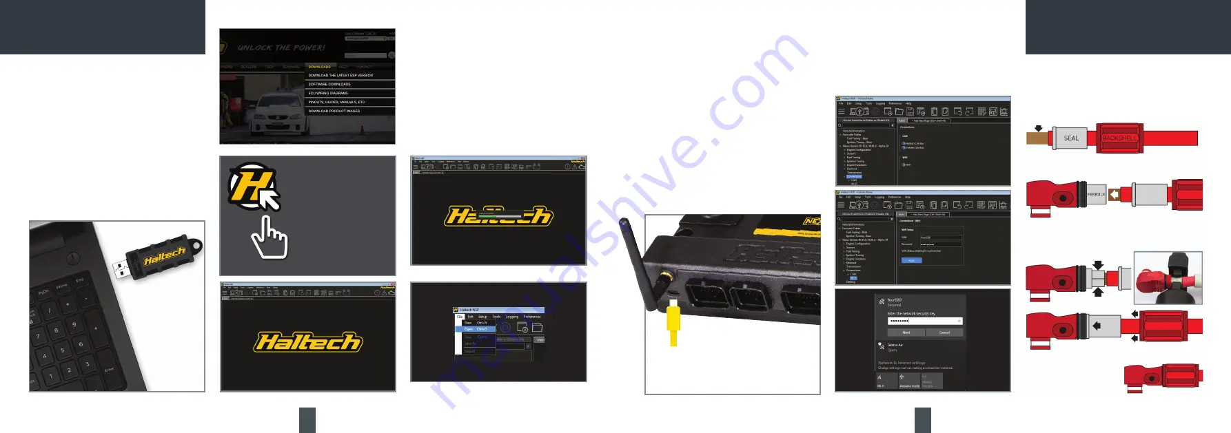
Installing the software

1.

 Insert the supplied USB Key into your PC.  If 

you have lost your USB key, you can download 
the Haltech NSP software from the DOWNLOADS 
section of the Haltech website.

2.

 If the window does not open automatically, open 

My Computer and find the USB drive. Double click 
on the USB drive icon.

3.

 Double click on the installer icon located in the 

root directory of the USB drive.

4.

 Once the Haltech NSP software is installed, run 

the software.

Going Online with the ECU

1.

 Plug the supplied USB-C cable into the USB-C 

Port on the front of the NEXUS R5.

2.

 The USB-C connection will power the ECU in a 

low power mode. 
This mode allows the user to connect to NSP for 
map configuration and data-log extraction without 
powering the ECU completely. ECU inputs and 
outputs are disabled in low power mode.

Setting up Wi-Fi communications

Wi-Fi communications can be enabled using NSP 
in the Wi-Fi Module Settings. 

When disabled, the module is held in an OFF state 
and is completely inactive. 

To set up your Wi-Fi connection follow these steps:

1.

 Open NSP and connect to your NEXUS R5 via 

the supplied USB-C cable.

2.

 Click on Connections in the feature tree and 

enable the Wi-Fi module setting.

3.

 Under Connections click on Wi-Fi to setup your 

SSID and password. Your SSID must be at least 1 
character and your password must be at least 8 
characters. 

3.

 NSP will recognise the ECU automatically.

4.

 Click File/Open to choose your base map.

NOTE:  The ECU must be powered on main power 
for Wi-Fi communication. Up to two computers 
may be connected to an ECU over Wi-Fi and one 
over USB-C at any one time.

Separate the backshell and seal from the Surlok 
connector body and slide them onto the cable to 
be crimped. Strip 20mm (3/4”) of sheathing from 
your 1AWG cable.

Insert your exposed cable into the Surlok 
connector ferrule.

Crimp ferrule and cable together using the 50mm 
die. Flip cable over to ensure ferrule is crimped 
completely.

Pull the seal over the ferrule then pull the 
backshell, tightening 
it onto the Surlok 
connector head.

4.

 Press Apply.

5.

 With the ECU powered up on main power go to 

your computer’s Network settings and connect to 
your NEXUS R5 by selecting your chosen SSID and 
typing in your password.

Summary of Contents for NEXUS R5

Page 1: ...1 QUICK START GUIDE...

Page 2: ...and Pins Set Male DTP06 4S Black connector 25A inc male plug female pins wedgelock seal HT 031201 Plug Set SurLok connectors red black 200A HT 030030 1AWG Battery Cable red black pair Pre terminated...

Page 3: ...operation on main power or low power mode Blue Connect to unit and install firmware Red Hardware fault DTC None DTCs not present Yellow A DTC is present of any kind past present not severe severe Blue...

Page 4: ...nnels per log 300 DIMENSIONS Enclosure Not including connector protrusion 257 x 132 x 51 mm 10 1 x 5 2 x 2 in Overall Including connector protrusion 257 x 163 x 61 mm 10 1 x 6 4 x 2 4 in Weight 1 50 k...

Page 5: ...ely inactive To set up your Wi Fi connection follow these steps 1 Open NSP and connect to your NEXUS R5 via the supplied USB C cable 2 Click on Connections in the feature tree and enable the Wi Fi mod...

Page 6: ...input and power up the ECU Method 2 instead of using the power for ignition switch pin the hot side of the ignition switch can simply be wired to any constant 12V source such that a 12V signal is dete...

Page 7: ...MOUNTING TEMPLATE MOUNTING TEMPLATE...

Page 8: ...ECU to an ignition module before setting the ignition firing edge correctly may damage the module and coils therefore it is advised to disconnect the module or disable the power to the ignition system...

Page 9: ...ide driven solenoids e g VTEC Solenoids high side switched automatic transmission solenoids etc Specs Capable of sinking 8A to ground and driving 8A to 12V Automatic Overcurrent and Overtemperature Pr...

Page 10: ...gger and Cam Home Inputs The crank and cam position sensors are required so that the ECU has the necessary information available to determine engine speed and position at any point in time Generally t...

Page 11: ...hstand Example Wiring Connections Example Wiring Connections Analogue Voltage Inputs AVI Analogue Voltage Inputs are inputs to the ECU that accept variable voltage signals from 0V to 5V such as signal...

Page 12: ...hicle Avoid sparks open flames or use of electrical devices near flammable substances Do not run the engine with a battery charger connected as this could damage the ECU and other electrical equipment...

Page 13: ...ail usa haltech com Haltech USA West Race Winning Brands 10800 Valley View Street Cypress CA 90630 USA Phone 1 888 298 8116 Email usa haltech com Haltech Europe Ottogasse 2A 2333 Leopoldsdorf Austria...

Reviews: