


Instruction Manual PSx3xx-PN
25
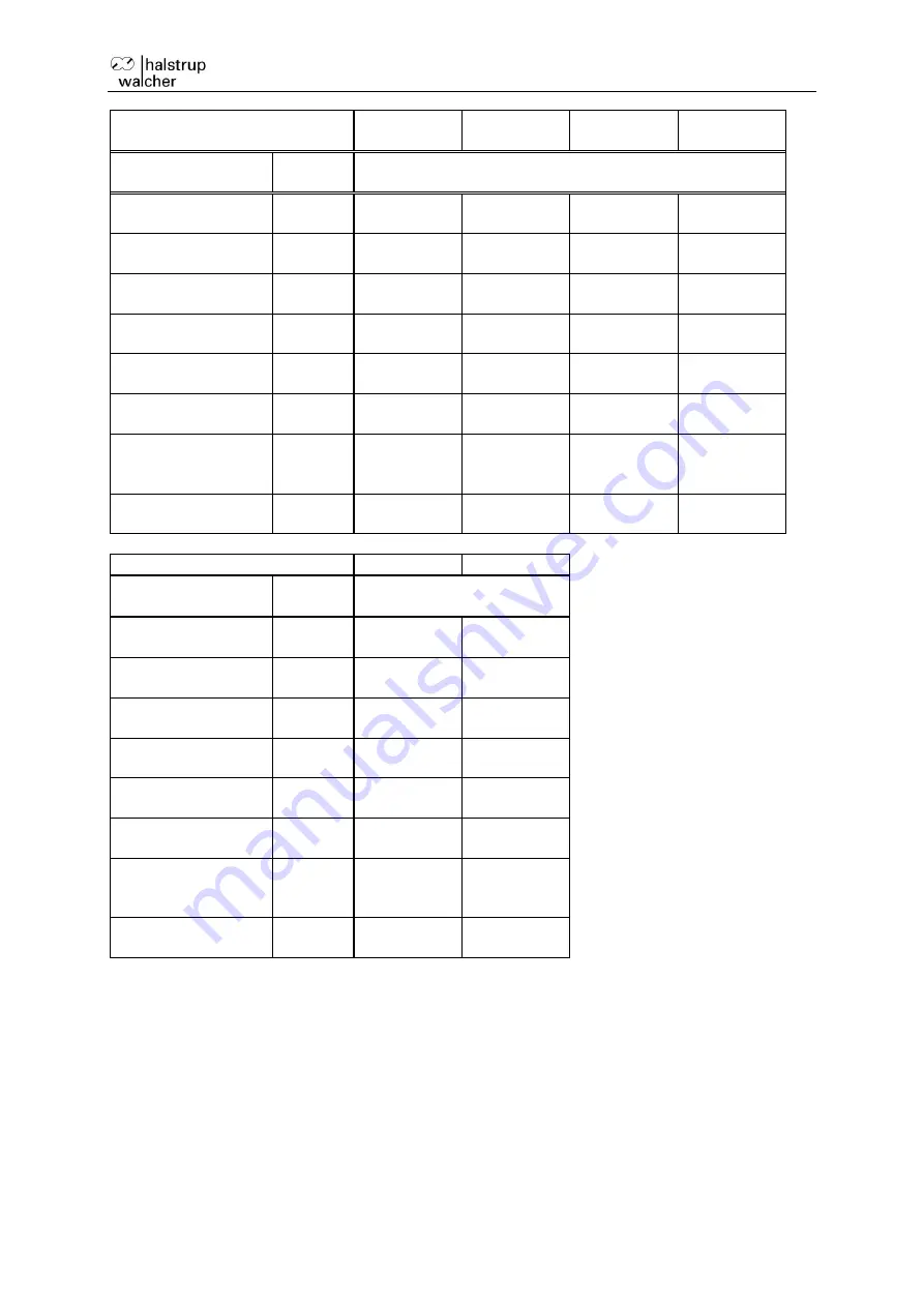
device model PSE
3110-14
3125-14
3210-14
3310-14
3218-14
Name
Par.-Nr.
value range
delivery state
target speed
53
1…30
30
1...12
12
5...45
38
3...30
28
target speed for
manual run
56
1…30
12
1...12
5
5...45
15
3...30
10
acceleration
58
9…50
50
4...20
20
20...117
117
11...70
70
deceleration
59
9…50
50
4...20
20
20...117
117
11...70
70
maximum start-up
torque
63
100...1200
1200
250...3000
3000
100...1200
1200
180...2200
2200
maximum torque
64
100...1200
1000
250...3000
2500
100...1200
1000
180...2200
1800
maximum holding
torque at end of
run
65
0...1200
400
0...2500
900
0...1000
350
0...1800
600
maximum holding
torque
66
0...600
200
0...1250
450
0...500
175
0...900
300
device model PSE
338-14
3325-14
Name
Par.-Nr.
value range
delivery state
target speed
53
8...85
55
2...18
15
target speed for
manual run
56
8...85
15
2...18
6
acceleration
58
37...200
200
8...45
45
deceleration
59
37...200
200
8...45
45
maximum start-up
torque
63
80...840
840
250...3000
3000
maximum torque
64
80...840
700
250...3000
2500
maximum holding
torque at end of
run
65
0...700
240
0...2500
900
maximum holding
torque
66
0...350
120
0...1250
450


