background image


DHP-UM-020 

Val Controls A/S 

 Limfjordsvej 3 

 DK-6715 Esbjerg N 

 Tel. +45 7547 0600 

 Fax +45 7547 0611 

[email protected] 

 www.valcontrols.com 

Revision: 12 


1/38 


USER MANUAL 


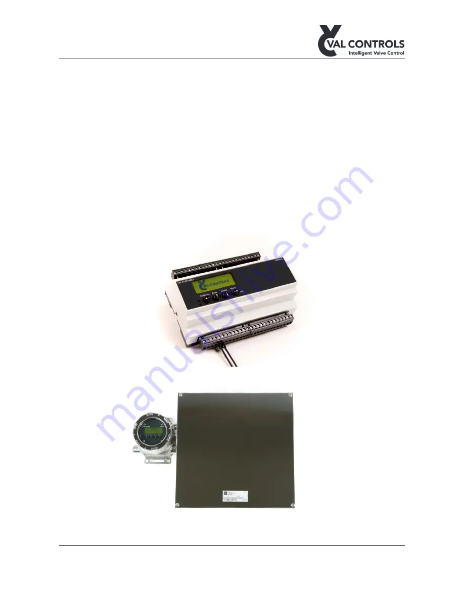
Intelligent Hydraulic Positioner 


IHP24-A 

IHP24-AF 

IHP24-B 

IHP24-BF 

IHP24-F 

IHP24-I 


Summary of Contents for IHP24-A

Page 1: ...A S Limfjordsvej 3 DK 6715 Esbjerg N Tel 45 7547 0600 Fax 45 7547 0611 vc valcontrols com www valcontrols com Revision 12 1 38 USER MANUAL Intelligent Hydraulic Positioner IHP24 A IHP24 AF IHP24 B IH...

Page 2: ...tion button and USB 9 4 5 Components 9 4 5 1 USB connector 9 4 5 2 Display 9 4 5 3 Keyboard 10 4 5 4 MT control 10 4 5 5 Status indicators 10 4 5 6 Indicator 10 4 5 7 Calibration button 10 4 5 8 TTL c...

Page 3: ...ion 3 17 Software ID DHP SW 0016 version 3 17 1 1 Safety instructions For a safe installation of a positioner the following must be observed The module shall only be installed by qualified personnel w...

Page 4: ...mitter loop signal is a 4 20mA signal with HART communication The control valve signals are powered through the 24VDC power supply and can supply valves up to 192W 48W each The position feedback from...

Page 5: ...controls com www valcontrols com Revision 12 5 38 Power supply Communication Hydraulic system Pump Pressure Return Supply 1 3 4 5 6 7 8 9 10 11 12 2 13 15 16 17 18 19 20 21 22 23 24 14 55 Valve Positi...

Page 6: ...d a Configure the valve function see 5 4 2 Advanced menu b Configure position feedback see 5 4 2 Advanced menu 3 Auto calibrate the unit by pushing CAL button or using ValConnect see 5 1 1 Automatic 4...

Page 7: ...interfaces which are described here 4 1 Display indicator and keyboard To control and monitor the device it is fitted with a graphical display four buttons and two indicators When the lid is removed a...

Page 8: ...m www valcontrols com Revision 12 8 38 4 2 Display keyboard indicator USB and status indicators This front is only available for type A Figure 5 Type A interface 4 3 Display keyboard indicator USB MT...

Page 9: ...e A and B interface Figure 8 Type F interface 4 5 Components 1 USB connector 2 Display 3 Keyboard 4 MT control sensors 5 Status indicators 6 Indicator 7 Calibration button 8 TTL connector 4 5 1 USB co...

Page 10: ...be set in the menu 4 5 5 Status indicators The functions of the seven indicators are as follows ESD The ESD input on the IHP is open Moving The valve is opening or closing Closed The valve is closed O...

Page 11: ...p to 1000 sec The automatic calibration is available for the standard and stepping regulator When the regulator type is set to proportional the auto calibration is automatic endpoint calibration Tunin...

Page 12: ...lue of the position loop TM mA mA value of the transmitter loop to control room Cnt DO1 Puls counter for DO1 Cnt DO2 Puls counter for DO2 Cnt DO3 Puls counter for DO3 Cnt DO4 Puls counter for DO4 DO1...

Page 13: ...7547 0611 vc valcontrols com www valcontrols com Revision 12 13 38 Status Description 3 Pump control Pump State of the pump Pressure Meassured pressure Switch Pressure switch state Level Meassure lev...

Page 14: ...e changed The positioner is still in service while these changes are made In the advanced menu more advanced parameters can be changed These parameters will change how the positioner is working and th...

Page 15: ...goes to stay put 5 Transmitter Transmitter settings 1 Transmitter action Transmitter action 1 Direct B A 0 flow 4mA 2 Reverse 0 flow 20mA 2 Transmitter fail position Transmitter fail 1 None B A During...

Page 16: ...til the position feedback is bigger than 5 Flow curve The valve characteristic expresses the flow percent through a valve at different opening angles To obtain an accurate regulation of the flow media...

Page 17: ...wide range of valves and still be able to obtain an accurate regulation The positioner needs 11 reference points to linearize an arbitrary valve characteristic Point 0 and point 10 cannot be entered...

Page 18: ...with increasing set point value Regulator Menu to set whether the regulator should keep opening or closing when within the deadband of 0 and 100 End settings Hold at Open o Status Off Never hold On H...

Page 19: ...and two positions None 3 5mA 0 2mA 21 5mA 0 2mA Display In this menu it is possible to turn the display light on off or set it to automatic When set on automatic the display light will turn on when us...

Page 20: ...uator 2 Close Not used A Menu to select valve position to close actuator 3 Stay put Not used A Menu to select valve position to keep current actuator position 4 Fail position Off A Menu to select valv...

Page 21: ...actuator can be opened and closed using the buttons When no button is pressed is the positioner in stay put mode Useful to check whether open and close are set correctly and to check if the system ca...

Page 22: ...Pulse to the open position Close Pulse to the close position o Open off time ext Extra time for pulse off times when opening o Close off time ext Extra time for pulse off times when closing o Open en...

Page 23: ...ump stop 120 bar 0 500 bar A Stop the pump when the pressure is above this value 3 Level 1 Loop Configuration if using a level transmitter 1 Pump stop 100 mm 0 9999 mm A Stop the pump when the level i...

Page 24: ...l Motor Safety Relay Set the relay input port When the port is disconnected the motor will stop running Max Running Time When the motor has been running for the specified period will an entry be made...

Page 25: ...as the input signal the user must configure at which level the pump must stop The levels returned from the sensor at 4mA and 20mA must be configured in the positioner There is a delay of 10 sec of th...

Page 26: ...mechanical stepping is to be done through ValConnect The recommended settings when setting up a IHP24 with a stepping actuator is Regulator type Mechanical stepping Dead band 2 Open on time 5 sec Clos...

Page 27: ...adjust the 2nd end point The following parameters can only be accessed through ValConnect Slow speed open Set the minimum speed when opening Slow speed close Set the minimum speed when opening Speed...

Page 28: ...6715 Esbjerg N Tel 45 7547 0600 Fax 45 7547 0611 vc valcontrols com www valcontrols com Revision 12 28 38 Acceleration time Slow speed Normal speed Slow speed dist Time sec Time sec Speed Position Se...

Page 29: ...r Trouble shooting Connect a potentiometer to the positioner Or Change the position feedback signal to position loop in the advanced menu 3 2 Consequence The positioner outputs goes to their fail posi...

Page 30: ...No 109 Analogue input loop 2 is not calibrated Description The analogue input loop 2 is not calibrated Trouble shooting Calibrate the analogue input loop 2 from the advanced menu 2 4 No 110 Analogue i...

Page 31: ...oting Calibrate the analogue output loop 2 from the advanced menu 2 9 No 120 Proportional output is not configured Description The proportional output signal has not been configured Only applicable wh...

Page 32: ...points Description The measured travel is not large enough Trouble shooting Increase the travel Check that the requirements for operating area 3 4 Electrical specifications for the position sensor or...

Page 33: ...meout Description A timeout occurred during the calibration Trouble shooting The system behaves in an unexpected way Slow down the system Restart the calibration No 208 Hold test failed Description Th...

Page 34: ...gue input 2 2 3 6 No 602 Pump control High temperature Description The measured temperature is above the specified values Trouble shooting Check the temperature of the oil Increase high temperature li...

Page 35: ...pressure error has been signalled to the positioner Decrease the pressure Increase the High High pressure limit No 607 Pump control Low temperature Description The measured temperature is below or bel...

Page 36: ...tor is still running Or increase the max running time in the menu Max running time 3 4 7 5 Communication No 8xx Communication error Description A communication error has occurred Trouble shooting See...

Page 37: ...ction o Fast detection of lost control loop Minor improvements Version 3 13 02 Minor improvements Version 3 13 03 New function o Delayed detection of reconnected control loop Version 3 14 00 Foundatio...

Page 38: ...front functionality inverted LED is ON when MT Control is unlocked Advanced reset renamed to Erase config Minor improvements Version 3 17 01 Minor improvements Version 3 17 02 Minor improvements Versi...

Reviews: