background image

4. Connect the extended nozzle hose assembly to the HaloFogger. Match the graphic icons - AIR / LIQUID - to 
ensure correct connection. Press connector coupling onto fitting until an audible ‘click’ is heard. 
5. Before beginning a fogging application, the extended nozzle assembly of the HaloFogger EXT must be 
primed. 

See instructions for priming the extended nozzle assembly.

6. Position the extended nozzle assemply within the space to be treated. Attach the nozzle assembly using 
the suction cup mount or use an accessory (i.e. tripod for example), then remove the nozzle cap.
7. To begin a fogging application process, reset the HaloFogger EXT by unplugging the device from the 
power source, then immediately reconnect. Confirm the status indicator light is illuminated green. Press and 
hold the Start button for two (2) seconds. The green status light will begin to flash red indicating you have 
thirty (30) seconds to leave the room before the unit begins to dispense disinfectant.
8. Leave room, close and seal door. Post sign on door indicating the room should not be entered during the 
treatment process.

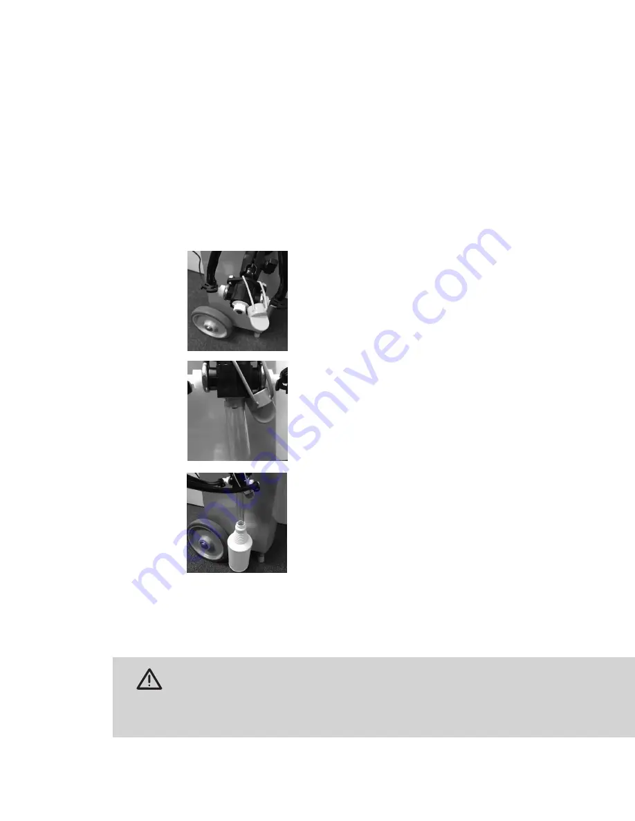
Instructions for Priming Extended Nozzle

1. Attach the ends of the HaloFogger EXT hoses to their respective air and 
fluid receptacles on the fogger. (See icons on fittings.)
        
2. Remove the protective nozzle cap from the nozzle.

3. Using the waste bottle provided, add one cup of tap water, then place it 
on the floor next to the rear wheel.


4. Take the clear tubing provided and drop one end into the waste bottle.


5. Working the adjustable ball joints of the nozzle assembly-mounting arm, 
point the nozzle straight down. Then move the nozzle assembly to the side 
of the HaloFogger EXT, locating the assembly above the waste bottle. 

6. Lower the nozzle assembly so the exposed end of the clear tubing 
engages the nozzle.  Then attach the nozzle assembly to the side of the 
fogger at that height using the suction cup mount.

7. Set the unit’s Fogging Timer for 10 minutes.

8. Press the start button and wait for the disinfectant to spray into the bottle.  
This may take up to  3 minutes.  When the disinfectant has started to spray 
consistently into the bottle stop the fogger by pressing the Start button 
twice in succession. The HaloFogger EXT is now primed and ready for 
fogging.

9. Remove the tubing the nozzle. Before moving nozzle assembly from side 
of fogger, place the protective nozzle cap back on the nozzle. Release the 
suction cup mount and relocate the fogger’s nozzle assembly to the desired 
application location within the room to be treated.

10. Discard liquid in waste bottle. Save bottle and clear tubing for next use.

CAUTION  
Hose Assembly will contain non-dispensed liquid disinfectant after priming and/or treatment is 
complete. Sudden movement of the hose assembly can allow captured liquid disinfectant to be released 
unexpectantly. Always replace the protective nozzle cap before moving the nozzle assembly. Always 
wear goggles and gloves when attaching/detaching the nozzle assembly and/or moving hose.

HaloFogger® EXT Operation Manual_1911

Summary of Contents for HaloFogger EXT

Page 1: ...READ AND SAVE THESE INSTRUCTIONS Operation Manual 110V 220V EXT 1911 EXT...

Page 2: ...n and dispensing disinfectant The room should be unoccupied Large Wheels For easy maneuvering Power Cord Connection Reservoir Drain High Precision Nozzle Dry mist of disinfectant is dispensed through...

Page 3: ...lashing or overfilling which could harm the user and or the device 12 Halosil International is not responsible for any injury or damage caused by using this device outside of the specific parameters d...

Page 4: ...ger EXT without the extended nozzle hose assembly fully connected Damage will occur Filling Instructions 1 Open the HaloFogger EXT Reservoir Door by lifting front edge of door 2 Locate the disinfectan...

Page 5: ...r wheel 4 Take the clear tubing provided and drop one end into the waste bottle 5 Working the adjustable ball joints of the nozzle assembly mounting arm point the nozzle straight down Then move the no...

Page 6: ...determine if the measured H2O2 level has dropped to about 1 ppm or below C If no written protocol has been established and you have no H2O2 sensor assume a waiting time of AT LEAST 110 MINUTES AFTER F...

Page 7: ...r data logger via Bluetooth The HaloLog App does not need to be connected to a fogger before a treatment run is started The on board data logger captures all of the operating data which can be reviewe...

Page 8: ...ll be displayed 4 To initiate a connection tap on any HaloFogger serial number displayed on the Halo List Screen When the connection is made the Run Events Screen will appear The top row of the screen...

Page 9: ...and total Run Time for that HaloFogger highlighted in GREEN The HaloLog data stored on the selected HaloFogger will download automatically after the Bluetooth handshake has been established which is...

Page 10: ...nts will identified BILLABLE as a default Events that are not treatments a test run for example can be identified as NON BILLABLE These events will not appear in the downloadable CSV file but will be...

Page 11: ...ddress A keyboard will appear to enter address ACTION Tap to email data The iDevice s email screen will open to confirm message ACTION Tap SEND in upper right corner of screen to send message Back up...

Page 12: ...o a HaloFogger 2 In the event that HaloLogs of the same HaloFogger have been downloaded to multiple devices If one user has made changes to the HaloLog for example added room building or operator info...

Page 13: ...remove Step 3 Separate Parts Remove Main Bolt from Nozzle Insert Soak both parts in soap and water Rinse parts thoroughly with water Step 4 Reassemble Nozzle Carefully insert the Main Bolt back into...

Page 14: ...power cord is plugged into both the fogger and the wall outlet Then check to see that the outlet is working The green status indicator light should be illuminated when properly set up The fuse is blow...

Page 15: ...sembly 0750 000 includes retainer cap nozzle insert main bolt and O ring Re Order Number Part Part Number 110V HaloFogger EXT US and Canada 0753 110EXT 220V HaloFogger EXT 0753 220EXT HaloMist All Pur...

Page 16: ...of room being treated CAUTION PRECAUCION DO NOT ENTER ENTERINO Room Fogging in Progress Treatment Date Start Time Estimated Room Re entry Time Refer to HaloMist Use Instructions to determine room re...

Page 17: ...was purchased and the unit s serial number Proof of purchase may be required If Halosil International determines that the fogger qualifies for warranty coverage a Return Merchandise Authorization RMA...

Page 18: ...uce infection rates at your facility by visiting www halosil com There you can find out more about the Halo Disinfection System download literature and case studies and find a distributor near you 91...

Reviews: