HAKKI PILKE RAVEN
TRANSLATION
VERSION 1-2015
Replacing and tightening the output conveyor belt
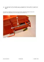
The instructions for tightening and aligning the output conveyor are presented in Section 4.6.
Replace the output conveyor belt as follows:
1.
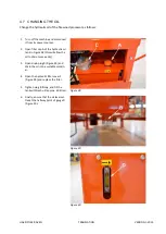
Pull out the pin locking the conveyor in place, and lower the conveyor to the ground.
2.
Turn off the machine and disconnect it from its power sources.
3.
Move the belt joint to the beginning of the conveyor.
4.
Fold the conveyor, but do not place the belt support in the transport position. This will allow the
belt to hang loose.
5.
Disconnect the joint by opening the bolts.
6.
Remove the old belt.
7.
First, insert the new belt under the folded conveyor (bottom opening) from the end of the convey-
or with the plates facing downwards. Feed the belt in until you can pull it out from the other end of
the conveyor. Pull out a length of approx. 60 cm.
8.
Push the other end of the belt into the upper section of the folded conveyor (top opening) from the
end of the conveyor. Feed it in until you can connect the joint.
9.
Pull the excess belt to the start of the conveyor.
10.
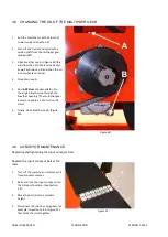
Open the conveyor to the operating position, and tighten and adjust the belt.
The belt is at the correct tension when its middle section is raised approx. 15 cm when the conveyor is in
the operating position. An excessively tight belt may be damaged more easily, and it places unnecessary
strain on the conveyor bearings.
Replacing the output conveyor plates
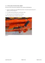
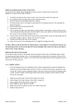
The output conveyor plates can be replaced by disconnecting the bolt joints (3 x M8) fastening the plates
and replacing the plates with new ones. It is recommended to move the belt into a position that puts the
plate to be replaced above the conveyor. Turn off the machine and disconnect it from the power source for
the duration of the procedure.
4.10 LUBRICATION
All of the firewood processor's lubrication points, which require Vaseline, have been labelled. The
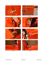
lubrication must be performed every 50 hours. There are nine lubrication points, presented in Fig-
ures 35–40. In order to access all grease nipples, remove the bolt pin and bolt of the lifting lug (Fig-
ure 35). Loosen the bolts circled in Figure 36 (or loosen them enough to slide the plate out) and
remove the cover plate.
1.
Nipples (2 pcs) of the saw control shaft in Figures 37 and 38.
2.
Grease nipple of the input conveyor drive roller in Figure 39.
3.
Grease nipple of the wood limiter in Figure 40.
4.
Guard nipples (2 pcs) in Figures 41 and 42.
5.
Nipples (2 pcs) of the output conveyor's drive roller in Figure 43.
6.
Nipples in Figures 44-47.


