background image

- 1 - 

Important Notice 

Manual 

Handling 

Keep this manual in a safe place where you can access it quickly. 


The Global Positioning System (GPS) consists of a total 24 GPS satellites that orbit the earth, 

enabling you to determine your position anywhere in the world, 24 hours a day, if you can receive 

satellite signals. During actual navigation, carefully compare the position data with all available 

navigation sources such as Loran C, Decca, other navigators, charts, visual navigation, depth, water 

temperature and others. It is your responsibility to make navigation judgments. 


The Electronic Chart : 

Only official authorized charts and notices to mariners contain all the information needed for the safety 

of navigation and, as always remember, the user is responsible for their prudent use. 


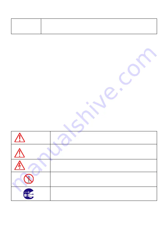
Pictorials 

This manual uses the following symbols for easy understanding safety instructions. Always follow 
these instructions carefully. 


WARNING 

Always follow this safety instruction to prevent death or injury. 


CAUTION 

Follow this safety instruction to avoid possible injury or damage to your 
property. 
Symbol “

” is a CAUTION or WARNING label indicating the safety 

instruction. 


WARNING 

This symbol is an Electrical Shock WARNING label. 


Symbol is an instruction that you must not violate. 
(This symbol instructs NOT to disassemble the system components) 


Symbol is an operation instruction that you must follow. 
(This symbol shows the main power OFF instruction.) 


Summary of Contents for Stella Series

Page 1: ...arts and notices to mariners contain all the information needed for the safety of navigation and as always remember the user is responsible for their prudent use Pictorials This manual uses the follow...

Page 2: ...r skin and eyes Do not use with poor ventilation If you cover this unit or use in an enclosed place it may malfunction or become damaged as a result of overheating Use only where there is sufficient v...

Page 3: ...s not to breath in dust during inspection or cleaning inside your system instruments Operation Notes For operators Observe the following operation notes otherwise the system failure or deterioration c...

Page 4: ...nstalled by authorized personnel Consult us for transducer installation by authorized personnel WARNING This product is designed to assist a navigation When you are sailing use the certified chart fro...

Page 5: ...For safety always resolve any uncertainty before continuing navigation CAUTION The Stella series employs the latest in proven technology to provide accurate navigation information The Plotter function...

Page 6: ...ity of the navigation source to provide accurate position information This device is only an aid to navigation It should be used in conjunction with all other navigation accuracy For safety always res...

Page 7: ...ash it off immediately in running water for 15 minutes If the liquid contacts your eyes immediately flush your eyes with running water for 15 minutes Contact a physician if any abnormal symptom is exp...

Page 8: ...8...

Page 9: ...e the chart of scale Open the menu Select the Goto function Select the configuration modification you wish Choose your favorite function Press to place a waypoint and access the waypoint option Press...

Page 10: ...10...

Page 11: ...entry Change the chart of scale and Setting up the depth range Open the menu Select the Goto function Select the configuration modification you wish Choose your favorite function Press to place a way...

Page 12: ...ey when plotter and Fish finder are displayed on the screen Turns the cursor on off QUICK NAV Uses instant navigation TRACK ON OFF Start and stop AIS tracks Vessel tracks WPT INPUT Press to place a wa...

Page 13: ...3 2 Turn off 1 3 2 Turn off Choose Power off on Fig 1 1 1 3 3 Restart Choose Restart on Fig 1 1 1 3 3 Adjust brightness Choose Brightness on Fig 1 1 1 3 4 Use day night mode Choose night mode on Fig 1...

Page 14: ...disappear on the screen and deactivate For activate keep pressing ToughLock 1 3 7 WiFi Choose WiFi on Fig 1 1 1 3 8 Bluetooth Choose Bluetooth on Fig 1 1 1 3 9 Data Layout Choose Data Layout on Fig 1...

Page 15: ...15 2 Specification of the connectors 2 1 Metal connectors...

Page 16: ...16 2 2 Plastic connectors...

Page 17: ...icon The present position Cursor Showing the cursor icon AIS target Showing the received AIS target Databar Showing various data on the top or bottom Cursor INFO The information of the cursor WPT INF...

Page 18: ...hosen colors Depth bar The current depth Low Frequency Showing 50KHz High Frequency Showing 200KHz LF INFO The information of Low Frequency 50KHz HF INFO The information of High Frequency 200KHz Datab...

Page 19: ...19 3 3 Navigation Data page 3 3 1 Navigation Data Type1 3 3 2 Navigation Data Type2...

Page 20: ...nt WPT name Direction of steer The best direction of the steering WPT icon The remaining distance of the WPT Vessel The out of the range from the best XTE Range The range of the XTE alarm Navigation D...

Page 21: ...21 3 5 Steering page WPT name Name of the WPT Direction of steer The best direction of the steering WPT icon Showing the WPT and the bearing Navigation Data Information of the various data...

Page 22: ...ition of SAT Position of the satellites SNB Graph Showing the WPT and the bearing Navigation Data Information of the various data Colors of the GPS status Black Tracked but no signal Blue Tracked but...

Page 23: ...has three meanings as below 4 1 1 GPS Showing the largest LAT LOT 4 1 2 HY Showing the LAT LOT SOG COG and userdata 4 1 3 HY2 Showing LON LAT mark track and time date 4 1 4 Customizing Showing variou...

Page 24: ...24 Fig 1 3 1 The databar is coming as Fig 1 3 1 and choose the frame with Four frames are available as Fig 1 3 2 Fig 1 3 2 When choosing the frame setting up in each box as Fig 1 3 3...

Page 25: ...tomizing for further question 4 2 Display MENU Advance Setup Customizing Databar Display Setting the databar Shown Hidden 4 3 Position MENU Advance Setup Customizing Databar Position Setting the datab...

Page 26: ...he cursor is moving to 5 3 Removing the cursor Press to remove the cursor 5 4 Cursor information window Latitude Longitude LAT LON of the cursor Range Distance between the cursor and the present posit...

Page 27: ...o finish Fig 1 4 6 1 Page mode MENU Advance Setup Customizing Page mode Two ways to choose the page 6 1 1 Standard With seeing the set up page choosing the page or modifying 6 1 2 Flip Showing the set...

Page 28: ...28 Fig 1 4 1 Fig 1 4 1 Choose your frame on Fig 1 4 1 Using key use and move the red box to choose the pages and press When you finish press Enter 1 Choose the pages with 2 Press choose with...

Page 29: ...29 Fig 1 4 2 Long press Choose the page and long press for drag the page into the frame Fig 1 4 3 When complete press Enter to finish 3 press Enter 4 Keep choosing and Enter to finish...

Page 30: ...30 7 Active ACTIVE When pressing FUNC the red box moves to to chartplotter or fishfinder All key functions change to chartplotter or fishfinder Selected red color...

Page 31: ...Steering page Highway page as Fig 1 5 Fig 1 5 8 1 Type MENU Advance Setup Customizing Navigation data Type Two types of Navigation data page 8 1 1 Type1 Large LAT LOT as Fig 1 5 1 Editing the LAT LOT...

Page 32: ...navigation data on the page editing the navigation data is unavailable MENU Advance Setup Customizing Navigation data Edit After finishing as Fig 1 5 3 press CANCEL to exit Please refer Customizing fo...

Page 33: ...tion Fig 1 6 9 1 Inputing Keep pressing WPT until the window comes out as Fig 1 6 and then MOB comes out with alarm 9 2 Exiting the alarm When alarming press CANCEL and you may exit the alarm 9 3 Remo...

Page 34: ...34 10 Memory Card Inserting the SD micro SD USB OTG as Fig 1 7 1 Fig 1 7 1...

Page 35: ...be inserted in the slot Userdata is in HY UserData 11 1 WPT WPT can be stored in a SD Micro SD USB When storing give it a name and you will be able to store many WPT in the SD Micro SD USB 11 2 Route...

Page 36: ...be stored in a SD Micro SD USB When storing give it a name and you will be able to store many user lines in the SD Micro SD USB 11 5 User Name User Name can be stored in a SD Micro SD USB When storing...

Page 37: ...ter loading the stored you will see the window and press MENU Second showing only stored WPT After loading the stored press ENTER 12 2 Route Route loads from the stored SD MicroSD USB All of route in...

Page 38: ...it 12 4 User Line User line loads from the stored SD MicroSD USB All of user line in the SD MicroSD USB show on the list Choose one of them and it will show 12 5 User Name User name loads from the st...

Page 39: ...39...

Page 40: ...shows up Choose one of them and you will exit If you have one WPT in the route the WPT will be stored If you have more than two all of WPT and the route will be stored together 1 2 Goto type2 1 2 1 Se...

Page 41: ...g all of the stored WPT Latitude Longitude LAT LOT of the WPT Name Name of the WPT Date Time Date and time of the WPT when stored Depth Depth of the WPT Bearing Bearing between the WPT and the present...

Page 42: ...42 2 2 Setting the WPT symbol MENU WPT Symbol Choose the symbol and press ENTER The chosen symbol will show when inputting WPT 2 3 Setting WPT Color MENU WPT Color Selected red color Selected red colo...

Page 43: ...ow the present position and current symbol color show for the WPT 2 4 1 Inputting on the chart Call the cursor and move the position where you want and press WPT The current symbol color show for the...

Page 44: ...he WPT list press 5 All Erase 1 Erase all Choose ALL of symbol and color and Erase and Enter 2 Erase by color and symbol Choose the color and the symbol and Erase and Enter 2 7 Moving the WPT 1 Call t...

Page 45: ...ou want to move and press ENTER 2 8 Navigating 2 8 1 Navigating on the list MENU Userdata WPT List 6 Goto Choose the WPT on the list and press 6 Goto 2 8 2 Navigating on the chart Call the cursor and...

Page 46: ...46 2 9 Move to vessel Call the cursor and move the WPT and Enter Choose Move to vessel...

Page 47: ...47 2 10 Sorting MENU Userdata WPT List 4 Sort Sorting the order of WPT on the list...

Page 48: ...ENU Userdata WPT List Editing the WPT on the list 1 Choose the WPT as the blue and press ENTER 2 Choose the item as the green and you may begin to edit 3 After finishing press CANCEL to exit Edit Sele...

Page 49: ...WPT Name Name of the route Number of WPT Number of WPT in the route Total distance Total distance of the route Display Shown Hidden the route on the chart Date Time Date and time of the WPT when stor...

Page 50: ...itude Longitude LAT LOT of the WPT Name Name of the WPT Date Time Date and time of the WPT when stored Depth Depth of the WPT Bearing Bearing between the WPT and the present position Range Distance be...

Page 51: ...e second is Creating new route on the list 3 3 1 Using GOTO Use GOTO type1 and create a route Press ENTER to start Press GOTO to exit and choose Store if needed 3 3 2 Creating new route on the list ME...

Page 52: ...the list to edit 3 5 Detail edit MENU Userdata Route List 4 Detail Choose the route on the list and press 4 Detail The window of Route detail shows 3 5 1 Adding WPT Two ways to add WPT 3 5 1 1 Adding...

Page 53: ...ENU Userdata Route List 6 Goto Choose the route on Route list and press 6 Goto 3 7 Erasing Choose the route and press 3 Erase 4 Track The maximum point is 50 000 Two ways to manage the track The first...

Page 54: ...ime Interval Setting the time interval 4 2 3 By distance MENU Userdata Track Track Setup Record Setup Distance Tracking by the set distance 4 2 4 Setting the distance interval MENU Userdata Track Trac...

Page 55: ...ws the number point of the track color 4 5 Track type 4 5 1 Type1 MENU Userdata Track Track Setup Type1 4 5 1 1 Erasing MENU Userdata Track Erase Choose the color and press ENTER The number next the c...

Page 56: ...56 4 5 1 2 Erasing all of track MENU Userdata Track Erase Press 1 All Erase 4 5 1 3 Erase with cursor MENU Userdata Track Erase Partial Erase Choose 2 Cursor Selected red color...

Page 57: ...57 Long press where you want to start erasing the track 1 should show on the left top...

Page 58: ...Track Track Setup Type2 4 5 2 1 Select index MENU Userdata Track Select Index Five rooms in the index The maximum is 10 000 points in each room In Type2 storing loading and erasing are available to ma...

Page 59: ...Time Date and time of the track room when stored Color Color of the track room On Off Track status on the index Display Show Hidden the track room Start Point The beginning of the track room End Poin...

Page 60: ...nts A and B 1 Call the cursor and move it on the point A 2 Call the cursor and move it on the point A 3 Move the cursor on the point B 4 The cursor windows provides the distance and bearing between A...

Page 61: ...cursor to the beginning point and press ENTER 4 Keep moving the cursor and press ENTER each time 5 Press CANCEL to exit 7 User Name Adding a place name directly on the chart 1 Call the cursor and mov...

Page 62: ...rection Offset When the chart position is wrong making it correct 1 Call the cursor and move it to the correct position 2 Press ENTER and choose Correction Offset The maximum range of Correction Offse...

Page 63: ...of the Main Screen while the map moves under it 1 3 Course Up MENU Advance Map Setup Map Orientation Up mode The Course Up mode screen orientation is determined by whether or not navigation is in prog...

Page 64: ...map scale on the display 2 5 Palette It is possible to the palette used to enhance the visibility of the screen depending on the surround light condition The possible choices are listed in the table b...

Page 65: ...Only for HY MAP mode 2 9 1 1 Depth Line Setting up 2m 5m 10m 20m 50m of the depth line on the HY MAP 2 9 1 2 Rock Setting up the Rock on the HY MAP The default setting is shown 2 9 1 3 Fishing Banks S...

Page 66: ...is drawn three times firstly it draws the two levels before the current level and then the current level The area covered by the cartographic data read from the previous levels is identified by a dott...

Page 67: ...Heading Line The length of the heading line is adjustable from 50 until 300 The bigger number the longer line The heading line is used in modes of the true motion and the north up The default setting...

Page 68: ...t setting is OFF 5 1 4 XTE Radius It is to adjust the range of the off course The default setting is 0 25nm 5 2 Anchor 5 2 1 Anchor Alarm It is necessary when your vessel anchors The default setting i...

Page 69: ...69 It alarms if it breaks into the setting area The default setting is OFF 5 4 2 User Line Range It sets the range of the course alarm The default setting is 0 05nm...

Page 70: ...and the tracked target based on your vessel s speed and direction and the target s speed and direction TCPA Time to Closest Point of Approach is the time remaining until the CPA will occur Name Name...

Page 71: ...eeping target is represented by a small oriented triangle Lost Target When the AIS info is not received from that vessel The presentation will be marked X on the target 3 AIS information window Press...

Page 72: ...72 4 Quick INFO on AIS target Choose AIS information window on Fig 3 1 and AIS data shows under the AIS target Up to four kinds of data is available to choose in Quick INFO...

Page 73: ...t setting is On 2 List 2 1 List Name Name of the AIS target MMSI MMSI of the AIS target CPA Distance between AIS target and your position COG BRG between AIS target and your position SOG Speed between...

Page 74: ...74 2 2 Detail Choose the AIS target and press ENTER...

Page 75: ...75 2 3 Goto Choose the AIS target and press 4 Find...

Page 76: ...76 2 4 Sort Press 3 Sort to choose how to sort on Fig 3 2 3 Display radius Displays range rings centered on your current position The default setting is OFF...

Page 77: ...rn on or off reception from different types of AIS transmissions for instance if you only wanted to view Class B vessels on the chart display then select Class B On and all the others Off 8 Alarm 8 1...

Page 78: ...8 8 Speed less than The values allowed are from 0 1kt to 9 9kt 9 Set up AIS outs etc 9 1 Mark vessels as lost after Setting the time of Lost target The default setting is 7min 9 2 Remove lost vessels...

Page 79: ...displayed on whatever screen you are viewing If the Status shows Test then no further action is required as it is just a test transmission If the Status shows Active it will also show the MMSI Name an...

Page 80: ...y in group fishing list 10 7 1 Group Fishing Highlight Showing the registered MMSI of AIS targets with the chosen color symbol Only Showing the registered MMSI AIS targets only 10 7 2 List Add Erase M...

Page 81: ...81...

Page 82: ...e frequency In dual frequency mode choosing the frequency with The chosen frequency shows in red 2 Auto Manual Gain Press ENTER to choose AUTO Manual of Gain 3 Gain STC Choose Gain and STC with 4 Cont...

Page 83: ...e active displays the sounder image with the surface at the top of the screen and the sea bottom in the lower part of the screen The depth scale indicates the depth range appearing in the display Bott...

Page 84: ...contour lines are added at intervals above the sea bottom to aid in determining distances of echoes near the bottom Use the Sounder Menu to set the magnified Bottom Range from 2 5 to 20m 10 to 60ft D...

Page 85: ...ishfinder image magnified for a short distance toward the surface A scale appears on the right for estimating distances of echoes near the bottom Use the Fishfinder Manu to set the magnified Bottom ra...

Page 86: ...86 6 4 Part Zoom Shows an enlarged fishfinder screen of the set range You can show the screen of left is normal screen and screen of right is part zoom...

Page 87: ...VRM WPT The VRM movable marker shown by the green line can be moved up and down It is convenient to measure the depth by aligning with the target such as school of fish Set the depth range it displays...

Page 88: ...past fishfinder When the cursor is called You can see past the screen using the key Then after WPT key is pressed the input position is marked in the past Input position is incorrect error range accor...

Page 89: ...he bottom range shall be 25m Th e default setting is 0m 1 4 Mode Fish finder modes are selectable for single frequency or dual and some functions 1 5 Bottom Zoom Range Select the range of the bottom z...

Page 90: ...1 8 Part Zoom You can set the depth range when using the part zoom 2 Advanced Menu MENU Advance 2 1 Display 2 1 1 A scope A scope shows the research under the water by a scope to see the environment u...

Page 91: ...the noise The default setting is On 2 1 10 Fish 2 1 10 1 Fish symbol Fish symbol with sizes and levels show for targets Fish symbol is only for reference This could be different from the real 2 1 10 2...

Page 92: ...eep Depth Range Setup the range of deep depth alarm The default setting is 0M 2 4 1 3 Shallow Depth alarm It alarms when the set shallow depth is out of the range The default setting is OFF 2 4 1 4 Sh...

Page 93: ...he default setting is 50m 2 4 3 4 Alarm Interval If the the alram is on It is available to setup the alarm interval The default setting is middle 2 4 3 5 Color Level If the the alram is on It is avail...

Page 94: ...A it is corrected by numeral setting 10 0 10 0 The default setting is 0 2 5 4 Draft set The tolerance of depth can be corrected The default setting is 0 0m 2 5 5 TD Setup Choosing the frequency of the...

Page 95: ...95...

Page 96: ...ion 1 4 LON Modification There could be a receiving signal error from satellites If it is on the longitude modify in the longitude modification 1 5 POG filtering Step 0 OFF 59 MAX the POG Filter When...

Page 97: ...m kt kilometer kilometers per hour km kmh yard knot yd kt cf 1nm 1 852km 1kt h 1 852km h less than 1nm display in yard and over 1nm display in mile Th e default setting is Nm Kt 2 1 2 Depth Select des...

Page 98: ...very the country 2 3 2 Time Format Sets you preferred time between 12 hour or 24 hour The default setting is 12 hour 2 3 3 Date Format Sets you preferred date among YY MM DD MM DD YY or DD MM YY The d...

Page 99: ...Cross track error measured OFF GPBOD Bearing origin to destination OFF GPBWC Bearing and distance to waypoint ON SYPLT Samyoung autopilot OFF 2 4 2 Transmit Available to adjust transmit speed of inpu...

Page 100: ...ype It is a select the navigation data type The default setting is Type1 2 7 1 5 2 Edit It customizes the Navigation data section except activated the fishfinder section 2 7 3 Menu 2 7 3 1 Type Two ki...

Page 101: ...as many as you want and those will show on the track color window 4 8 5 3 Selection Method Choose mark symbol color and track color Standard Available to choose a symbol and color Flip rotation of sy...

Page 102: ...upgrade 3 4 Simulator It is necessary for an indoor demonstration The simulations of GPS Fish finder or AIS in the memory 3 5 Language Select the language 3 6 Remote control settings 3 6 1 Remote con...

Page 103: ...ide 5 Others 5 1 Screen capture This is the function of save the current screen Note The capture file is stored in external SD card The storage location is HY Capture in SD card 5 2 Capture List Avail...

Page 104: ...Setting the data layout on the screen Only available in Shown Standard is Hidden 2 EDIT 2 1 Move Available to move the layout data with drag and drop Touch EXIT to finish Available when more than one...

Page 105: ...e layout Position SOG and COG 2 3 Time Date Showing the layout Time and Date 2 4 Userdata Display Showing the layout WPT and Track 2 5 Fishfinder Showing the layout Depth and Temp 2 6 Unspecified Show...

Page 106: ...8 dBm Tracking 165 dBm Reacquisition 162 dBm 5 Nav Update 1Hz 5Hz 6 Support DGPS SBAS EGNOS WAAS MASA GAGAN Chartplotter specification 1 Display Method Mercado Projection 2 Display Mode True motion N...

Page 107: ...107 Standard Equipment Configuration List Display unit External GPS ANT option Manual Protector Mounting Bracket Knobs Fuse Bolt Remote control option Power cable Dimension...

Page 108: ...v Update 1Hz 5Hz 6 Support DGPS SBAS EGNOS WAAS MASA GAGAN Chartplotter specification 1 Display Method Mercado Projection 2 Display Mode True motion N S E W up Course up Head up 3 Latitude Limits Betw...

Page 109: ...ion Interferences rejection 3 levels Noise rejection 4 levels 7 Function Gain auto manual Range auto manual Depth with shift auto manual Pulse length selection White Black line Water temperature Suppo...

Page 110: ...8 dBm Tracking 165 dBm Reacquisition 162 dBm 5 Nav Update 1Hz 5Hz 6 Support DGPS SBAS EGNOS WAAS MASA GAGAN Chartplotter specification 1 Display Method Mercado Projection 2 Display Mode True motion N...

Page 111: ...111 Standard Equipment Configuration List Display unit External GPS ANT option Manual Protector Mounting Bracket Knobs Fuse Bolt Power cable Remote control option Dimension...

Page 112: ...Update 1Hz 5Hz 6 Support DGPS SBAS EGNOS WAAS MASA GAGAN Chartplotter specification 1 Display Method Mercado Projection 2 Display Mode True motion N S E W up Course up Head up 3 Latitude Limits Betwe...

Page 113: ...ion Interferences rejection 3 levels Noise rejection 4 levels 7 Function Gain auto manual Range auto manual Depth with shift auto manual Pulse length selection White Black line Water temperature Suppo...

Page 114: ...Present water temperature TOT TIME Total Time Total using time VOLTAGE Present voltage unstable voltage shows in red TTG Time To Goal Remaining time to the destination ETA Estimated time of arrival XT...

Page 115: ...sidered dangerous to surface navigation Marine farm Lighthouse Wreck depth unknown which is considered dangerous to surface navigation Military restricted area into which entry is prohibited Radar tra...

Page 116: ...the surface to permit through bolt fastening for the mounting bracket Display Unit Installation Temporarily install the mounting bracket on the Genesis display unit and place the unit at the selected...

Page 117: ...117 place to prevent damage during the rest of the installation process Mounting Bracket Flush Mounting...

Page 118: ...minal is not available install an in line fuse holder Care and Cleaning Stella series is made to withstand marine elements but a little care ensures a trouble free life Accumulations of salt and sand...

Page 119: ...e time of printing Please refer to the appropriate NMEA specifications for details and the latest information The data sentences used by the HGP 660 are as follows Output sentences Descriptions Conten...

Page 120: ...etermine your position in relation to a set of satellite o rbiting the earth The GPS constellation of satellites continuously send radio signals containing the precise position for each satellite back...

Page 121: ...of the inmarsat 8 Over 3m away form the ANT of the roof 9 Over 2m away from the engine 10 Over 0 5m away from the metal surface Warning Not less than 0 5m away from the metal surface If the environmen...

Page 122: ...that orbit the earth Signals are required from 3 satellites for two dimensional 2D position calculation whilst 4 satellites are required for three dimensional 3D position calculation As mentioned earl...

Page 123: ...accurate distances to the satellites using the Spread Spectrum Modulation method Excellence in GPS s position fixing accuracy i s mainly due to this technology 3 When the satellite locations and thei...

Page 124: ...n the contrary accuracy is reduced when the satellites have gathered in a narrow space In the follow ing figure in both cases it is possible to obtain the GPS fix but in the left case the accuracy wil...

Page 125: ...nsors and for different beam angels and sonar frequencies Several different transducers may be used with the HD 50 SERIES Refer to the optional Equipment list for the variations available CAUTION Moun...

Page 126: ...installation is completed Route the transducer cable as far as possible away from the boat s power cables engine controls and other electrical cables Do not route transducer cables near your VHF radio...

Page 127: ...n the center third of water line length at cruising speed are usually satisfactory Locations forward of the engine and in a flat area near the center line of the boat are preferred Do not install the...

Page 128: ...l be adversely affected by accumulations of sea growth on the face of the transducer To prevent sea growth effects the face of the transducer may be coated with antifouling paint specially formulated...

Page 129: ...he transducer The bronze housing may be coated with any antifouling paint If fairing blocks are used especially if made of wood complete sealing prior to painting is important Marine Sealant Stem Fixi...

Page 130: ...ION DWG NO DES BY NONE SCALE PER N MODEL CHK BY MATERIAL DRA BY Y S KIM OLIX CO LTD DATE 05 07 2012 Smart Series Y S KIM Power Cable S7 DC10303M Y S KIM Y S KIM 16 03P Red Black NOTE 2 1 3 2 1 BLACK R...

Page 131: ...PER N MODEL CHK BY MATERIAL DRA BY Y S KIM OLIX CO LTD DATE 05 07 2012 Smart Sereis Y S KIM Data Cable S7 DC10103M Y S KIM Y S KIM To HD 70 series J2 J3 16 06P Shrinking Tube 20 Shrinking Tube 15 00 7...

Page 132: ...CTION PIN WIRE COLOR Power Calbe 2 4 3 5 7 6 8 1 Kim Y S Kim Y S Kim Y S DRA BY Park D J Smart Series CHK BY PER N DES BY MODEL MATERIAL SCALE 1 2 2012 05 07 DATE OLIX CO LTD S7 DC10301P DESCRIPTION D...

Page 133: ...133 KIM Y S KIM Y S KIM Y S D J PARK S7 PA90101 Smart Series DESCRIPTION DWG NO DES BY 1 1 SCALE PER N MODEL CHK BY MATERIAL DRA BY GPS ANT OLIX CO LTD DATE 2012 05 07...

Page 134: ...DRA BY Souk J E CHK BY PER N DES BY 2014 02 05 DATE DWG NO DESCRIPTION NONE SCALE MATERIAL MODEL Smart Series mark option OLIX CO LTD Transduser 1 SPD_PULSE 2 SPD_VCC 3 TD1 4 TD_GND 5 TD2 6 TEMP_VCC 7...

Page 135: ...Y S Kim Y S DRA BY Souk J E CHK BY PER N DES BY 201 02 05 DATE DWG NO DESCRIPTION NONE SCALE MATERIAL MODEL Smart Series mark option Transduser 1 SPD_PULSE 2 SPD_VCC 3 TD1 4 TD_GND 5 TD2 6 TEMP_VCC 7...

Page 136: ...fter a user purchases the product within one 1 year 2 Accessories One 1 year for consumed accessories including TD after a user purchases them Service in Charge 1 Over the term from the guarantee 2 Da...

Reviews: