background image

– 39 –

Replacing Sealed System Components

  Evacuation and Charging Procedure

The following information covers the evacuation and charging procedure for sealed system work. 

WARNING:

‡

Before cutting or using a torch on refrigerant tubes, recover the refrigerant from the system using 
approved recovery equipment.

‡

Never charge new refrigerant through the purge valve. This valve is always located on the high 
pressure side of the system.

‡

Never apply heat from any source to a container of refrigerant. Such action will cause excessive 
pressure in the container.

‡

Always wear appropriate PPE (Personal Protective Equipment) when working with refrigerants and 

nitrogen holding a charge in some replacement parts. Contact with these gases may cause injury.

1.  Evacuate the system to ~20-in. vacuum using the refrigerator compressor and/or recovery pump.

2.  Purge the system using nitrogen at 25-35 SCFH.

3.  Perform necessary repairs to the sealed system.

4.  Pressurize the system to 250 PSIG with nitrogen and test for leaks.

5. 

2QFH FRQ¿UPHG WKDW QR OHDNV DUH SUHVHQW HYDFXDWH WKH QLWURJHQ DQG XVH WKH FRPSUHVVRU WR SXOO

the system back into a vacuum. 

6. 

&KDUJH WKH V\VWHP ZLWK WKH H[DFW DPRXQW RI UHIULJHUDQW VSHFL¿HG RQ WKH QDPH SODWH RU VSHFL¿HG RQ

the instruction sheet included with the component being replaced.

7.  Reinstall caps to Schrader ports.

Summary of Contents for GE ABE21D

Page 1: ...GBE21D ABE21D 2016 Artistry GE Swing Door Refrigerators Technical Service Guide March 2018 31 9285 ...

Page 2: ...ctrical power is required for diagnosis or test purposes disconnect the power immediately after performing the necessary checks RECONNECT ALL GROUNDING DEVICES If grounding wires screws straps clips nuts or washers used to complete a path to ground are removed for service they must be returned to their original position and properly fastened GE Appliances a Haier Company Copyright 2018 All rights ...

Page 3: ...r Supply Line 9 Operation 10 LUÀRZ 11 Refrigerator Door 12 Refrigerator Door Handle 12 Refrigerator Door Bins 12 Refrigerator Gasket 12 Refrigerator Door Removal 13 Refrigerator Door Bottom View 13 Freezer Door 14 Freezer Door Handle 14 Freezer Gasket 14 Freezer Door Removal 15 Freezer Door Bottom View 15 Refrigerator 16 Refrigerator Interior Component Locator 16 Adjustable Shelves 17 Climate Cont...

Page 4: ...itch 24 Evaporator Fan Cover 24 Evaporator Cover 25 Evaporator Fan 25 Icemaker Fill Tube 26 Evaporator Components 27 Defrost Thermostat 28 Defrost Heater 28 Evaporator Thermistor 29 Evaporator 30 Defrost Operation 31 Adaptive Defrost 31 Pre Chill 31 Defrost Heater Operation 31 Dwell 31 Post Dwell 31 Abnormal Defrost 31 Main Board 32 Main Board Connector Locations 33 Machine Compartment 34 Machine ...

Page 5: ... 5 Condenser Fan 35 Condenser 36 Compressor Electricals TSD 36 Compressor 37 Drier 37 Cooling System 38 Replacing Sealed System Components 39 Evacuation and Charging Procedure 39 Schematic 40 Index 41 ...

Page 6: ...arge stored energy Step 3 Isolate the appliance Step 6 Try It verify that the appliance is locked out GE Factory Service Employees are required to use safety glasses with side shields safety gloves and steel toe shoes for all repairs Steel Toed Work Boot Electrically Rated Glove and Dyneema Cut Resistant Glove Keeper Dyneema Cut Resistant Glove Cut Resistant Sleeve s Plano Type Safety Glasses Braz...

Page 7: ...CT V NOV Z DEC 2024 Z 2023 V 2022 T 2021 S 2020 R 2019 M 2018 L 2017 H 2016 G 2015 F 2014 D 2013 A Model Number A B E 2 1 D G K A R B S Brand A Artistry G GE RQ JXUDWLRQ B Bottom Freezer Finish G High Gloss Model Year 2016 Handle Color S Stainless Steel B Black W White Door Swing R Right Engineering Digit Energy Star E Energy Star Capacity 21 Cubic Feet Feature Pack Exterior Color S Stainless Stee...

Page 8: ... VDC FZ LED Boards 3 VDC FF Temperature Board 2 5 VDC 21 CU FT SWING ELECTRONIC BOTTOM FREEZER ABE21 GBE21 REFRIGERATION DIAGNOSIS To access the low pressure side of the system install a WJ56X61 valve only on the process tube extending from the compressor case REFRIGERATION SYSTEM Compressor 710 BTU hr Minimum Compressor Capacity Vacuum 22 inches Minimum Equalized Pressure 70 F 40 45 PSIG 90 F 48 ...

Page 9: ...ng legs Each front corner has a leveling leg to help adjust the side WR VLGH KHLJKW DQG UPO SRVLWLRQ WKH UHIULJHUDWRU which prevents it from moving Leveling legs should be set so the front of the refrigerator is raised just enough that the doors close easily when opened half way Water Supply Line A water supply line will be needed for the installation of the optional icemaker Recommended copper wa...

Page 10: ...ent temperature The fresh food temperature is preset in the factory at the Colder position Allow 24 hours for temperature to stabilize to the preset recommended setting NOTE 7KH FRROLQJ V VWHP FDQ EH WXUQHG Rႇ E WXUQLQJ WKH UHIULJHUDWRU WHPSHUDWXUH FRQWURO NQRE WR WKH 2ႇ SRVLWLRQ Knob Position Temperature Guide Refrigerator Freezer Coldest 34 F 1 1 C Coldest 6 F 21 1 C Colder 37 F 2 8 C Colder 0 F...

Page 11: ... 11 LUÀRZ ...

Page 12: ...new end caps Vertical GBE21 Door Handle Removal 1 Slide the handle up to release it from the mounting fasteners 2 Pull the handle away from the door Refrigerator Door Bins Door bins are removable by lifting up on the desired bin Refrigerator Gasket The refrigerator door gasket is a push in style gasket which allows for easy removal and installation into a retainer channel molded into the door The ...

Page 13: ...ead screws securing the right hinge covers to the case 3 Flip the covers over to access the top hinge 4 Remove three 5 16 in hex head screws 5 LIW WKH XSSHU KLQJH Rႇ WKH GRRU DQG OLIW WKH GRRU Rႇ WKH PLGGOH KLQJH Refrigerator Door Bottom View Closure Hinge Bushing Door Stop ...

Page 14: ...the cabinet Freezer Door Handle There are two types of door handles depending RQ WKH PRGHO RWK KDYH D GLႇHUHQW UHPRYDO method Horizontal ABE21 Door Handle Removal 1 Remove the chrome end cap that is on the ÀDW SDUW RI WKH KDQGOH DGKHUHG ZLWK GRXEOH sided tape to reveal two Phillips head screws 2 Loosen the 1 8 in set screw in the bottom or top depends on the door swing of the handle The set screw ...

Page 15: ...gerator door removal steps 1 to 5 2 Use a 1 4 in Allen wrench to remove the hinge pin from the middle hinge 3 Tilt the door away from the cabinet then lift the GRRU Rႇ WKH ERWWRP KLQJH Freezer Door Bottom View Closure Hinge Bushing Door Stop ...

Page 16: ... 16 Refrigerator Refrigerator Interior Component Locator FF LED Board Adjustable Shelves FF Door Switch Control Housing Assembly Air Tower Climate Controlled Pans FF Thermistor Vegetable Pan Cover ...

Page 17: ...the drawer up and past the stop position and pull forward FF Door Switch The refrigerator FF door switch is located under the right hinge covers When the refrigerator door is opened the normally closed contacts of the switch close permitting 120 VAC to reach J7 pin 6 on the main board Once the voltage is sent to the main board voltage is then supplied to the FF LED board FF Light Switch Diagnosing...

Page 18: ...the light shield to release two tabs at the rear of the shield and remove the light shield 2 Remove two 1 4 in hex head screws from the front of the LED board 3 Pull the LED board towards the front of the cabinet to release the rear tabs that are inserted into the top of the cabinet 4 Disconnect the two pin connector and pay attention to the FF thermistor and thermistor IRDP EORFN DV WKH IRDP EORF...

Page 19: ...white black FF Thermistor Removal Replacement 1 Follow FF LED Board Removal steps 1 through 4 under FF LED Board in this section of the service guide 2 Remove the thermistor from the foam block 3 Cut the thermistor wiring as close to the thermistor as possible 4 Using two bell connectors Part WR01X10466 splice the wiring After the VSOLFHV DUH FRPSOHWH OO WKH EHOO FRQQHFWRUV fully with silicone gre...

Page 20: ...s control knobs a freezer manual damper control housing cover and a FF temperature control board Freezer temperature is not electronically controlled When the freezer control knob is turned to a colder position it is lowering a manual GDPSHU WR UHVWULFW WKH DLU ÀRZ LQWR WKH UHIULJHUDWRU VHFWLRQ 7KH UHGXFHG DLUÀRZ FDXVHV WKH thermistor in the refrigerator section to take ORQJHU WR EH VDWLV HG WKXV ...

Page 21: ...pin 8 red silver 12 VDC J4 pin 3 blue to J1 pin 7 red white 5 VDC J4 pin 3 blue to J1 pin 7 red white Refrigerator set to Coldest setting 4 6 VDC Refrigerator set to Colder setting 3 3 VDC Refrigerator set to Cold setting 2 5 VDC 5HIULJHUDWRU VHW WR 2ႇVHWWLQJ a 9 If the main board does not receive any voltage from the FF temperature board the compressor and fans will not operate FF Temperature Boa...

Page 22: ... 22 Freezer Interior Component Locator Freezer Light Switch FZ LED FZ LED Fill Tube Receptacle Cover Evaporator Fan Cover Basket Wire Shelf ...

Page 23: ...XS ZLOO FRPH LQ WKH 0 NLW EXW LW VKRXOG not be used because it will not align with the OO WXEH 7KH FRUUHFW OO FXS FRPHV ZLWK WKH refrigerator shipped in the handle pack Should WKH OO FXS EH PLVVLQJ RU GDPDJHG D QHZ OO FXS FDQ EH RUGHUHG 7KH OO FXS FDQ EH IRXQG E looking the refrigerator model number up in the illustrated parts catalogue ON OFF Switch Feeler Arm Icemaker Diagnosing The icemaker can...

Page 24: ...the top away from the liner 2 Pull the switch from the liner 3 Disconnect the red and brown wires Freezer Light Switch Freezer LEDs The freezer has two LED boards one on each side of the freezer Freezer LED Diagnosing from left LED with freezer light switch not pressed Red silver to white silver 12 VDC Pink to white silver 3 VDC Pink to red silver 10 VDC Freezer LED Diagnosing from right LED with ...

Page 25: ...the fan connector 5 Remove two 1 4 in hex head screws 6 Pull the evaporator cover out of the freezer Evaporator Fan The main board operates the evaporator fan at a target speed of 2 200 RPMs The fan provides 530 IHHGEDFN WR WKH PDLQ ERDUG WR FRQ UP IDQ speed Evaporator Fan Diagnosing Main Board J4 pin 2 red yellow to J2 pin 3 white silver 12 VDC constant supply J2 pin 1 blue to J2 pin 3 white silv...

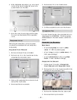
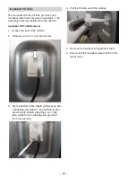
Page 26: ...ss the rear of the cabinet 2 Remove one 1 4 in hex head screw 3 Pry the bottom of the plastic grommet up with D ÀDW EODGH VFUHZGULYHU 7KH OO WXEH LV DOVR secured with double sided tape so it may take a little force to dislodge the grommet from the opening 4 3XOO WKH OO WXEH RXW RI WKH FDELQHW 5 Remove the machine compartment cover 6 Disconnect the icemaker water line from the water valve ...

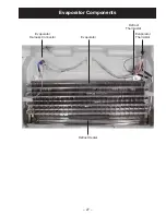
Page 27: ... 27 Evaporator Components Evaporator Harness Connector Evaporator Thermistor Evaporator Defrost Thermostat Defrost Heater ...

Page 28: ...stat can be replaced individually or as part of the evaporator harness 4 If replacing the thermostat as part of the evaporator harness disconnect the 6 pin cabinet connector and the defrost heater connectors If replacing the thermostat by itself proceed to the next step 5 Cut the thermostat wiring as close to the thermostat as possible 6 Strip the two wires back 3 16 inch for splicing 7 Prepare th...

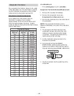
Page 29: ...om the outlet tube of the evaporator NOTE The evaporator thermistor can be replaced individually or as part of the evaporator harness 4 If replacing the thermistor as part of the evaporator harness disconnect the 6 pin cabinet connector and the defrost heater connectors If replacing the thermistor by itself proceed to the next step 5 Cut the thermistor wiring as close to the thermistor as possible...

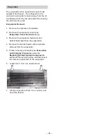
Page 30: ... evaporator cover see Evaporator Cover Removal steps 3 Remove the evaporator thermistor and defrost thermostat from the evaporator 4 Remove the defrost heater with evaporator harness from the evaporator 5 Follow recovery procedure see Evacuation and Charging Procedure under the Replacing Sealed System Components section of this service guide and disconnect the inlet and outlet lines of the evapora...

Page 31: ...U LV RQ XQWLO WKH evaporator thermistor temperature reaches 55 F or until the heater on time reaches 40 minutes ZKLFKHYHU KDSSHQV UVW Adaptive Defrost Pre Chill Defrost Heater Operation Adaptive Defrost is a defrost system that adjusts to a refrigerator s surrounding environment and household usage Unlike conventional defrost systems that use electromechanical timers with a HG GHIURVW F FOH WLPH G...

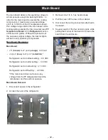
Page 32: ...ard Diagnosing Main Board J11 brown to J7 pin 9 orange 120 VAC J4 pin 3 blue to J1 pin 7 red white Refrigerator set to Coldest setting 4 6 VDC Refrigerator set to Colder setting 3 3 VDC Refrigerator set to Cold setting 2 5 VDC 5HIULJHUDWRU VHW WR 2ႇVHWWLQJ a 9 If the main board does not receive any voltage from the FF temperature board the compressor and fans will not operate Main Board Removal 1 ...

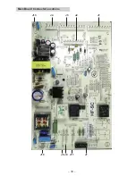
Page 33: ... 33 Main Board Connector Locations J10 J8 J11 J13 J4 J3 J1 J2 J7 J9 ...

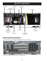
Page 34: ...ssor Drain Tube Icemaker Water Valve Connector Process tube Rear Wheel x2 Suction Line Condenser Fan Shroud Test Jack Machine Compartment Cover Removal 1 5HPRYH RQH LQ KH KHDG VFUHZ DQG YH LQ KH KHDG VFUHZV 2 Lift the cover up to remove the cover from the base pan 1 4 Screw ...

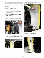
Page 35: ...ilver to J2 pin 5 yellow red 12 VDC Condenser Fan Removal 1 Remove the machine compartment cover 2 Remove the drain tube from the cabinet 3 Unclip the wire tire securing the top of the condenser fan shroud to the condenser coil there is no need to replace the wire tie during reassembly 4 Remove the 1 4 in hex head screw at the bottom of the shroud 5 Disconnect the fan connector 6 Pull the shroud a...

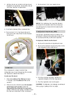
Page 36: ...m Components section of this service guide and disconnect the inlet and outlet lines of the condenser 3 Remove two 1 4 in hex head screws NOTE The condenser fan mounting bracket connected to the bottom left of the condenser coil will need to be reused when replacing the condenser coil Compressor Electricals TSD Compressor electricals shown as TSD in the schematic in this service guide are made up ...

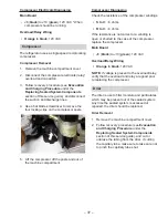
Page 37: ... replaced Drier Removal 1 Remove the machine compartment cover 2 Follow recovery procedure see Evacuation and Charging Procedure under the Replacing Sealed System Components section of this service guide and cut or unbraze the tubing from the drier If cutting the capillary tube make sure to take care not to pinch the capillary tube shut Compressor Diagnosing Check the resistance of the compressor ...

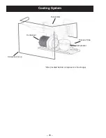
Page 38: ... 38 Cooling System Condenser Loop Condenser Evaporator Drier located behind compressor in this image Process Tube Compressor ...

Page 39: ...r appropriate PPE Personal Protective Equipment when working with refrigerants and nitrogen holding a charge in some replacement parts Contact with these gases may cause injury 1 Evacuate the system to 20 in vacuum using the refrigerator compressor and or recovery pump 2 Purge the system using nitrogen at 25 35 SCFH 3 Perform necessary repairs to the sealed system 4 Pressurize the system to 250 PS...

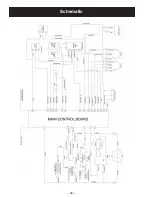
Page 40: ... 40 Schematic ...
Page 41: ...12 14 Door Stop 13 15 Drain Tube 34 Drier 34 37 38 E Evaporator 22 24 25 27 28 29 30 38 Evaporator Fan 22 24 25 Evaporator Harness 27 Evaporator Thermistor 27 29 F FF Door Switch 16 17 FF Temperature Board 20 21 FF Thermistor 16 19 Fill Cup 23 Fill Tube 22 26 Freezer Gasket 14 Freezer Light Switch 24 FZ LED 22 H Hinge Bushing 13 15 hinge pin 15 I Icemaker 23 26 34 L LED Board 16 18 M Main Board 17...

Reviews: