31-5000564 Rev. 1
41
FRANÇAIS
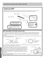
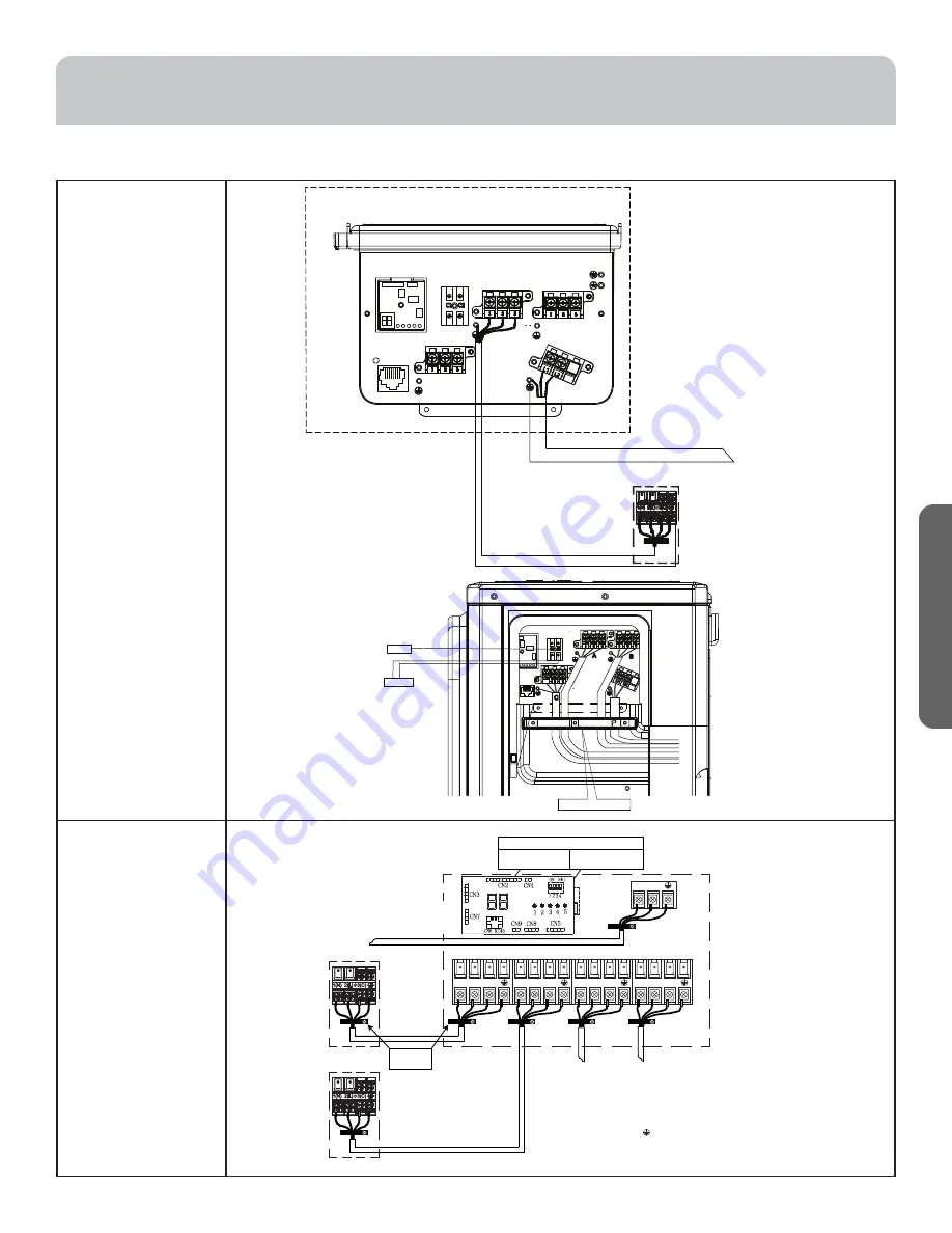
Étape 3 – Installation de l’unité extérieure (Suite)
INSTRUCTIONS D’INSTALLATION
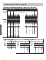
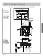
Modèle :
2U18MS2HDA1
3U24MS2HDA1
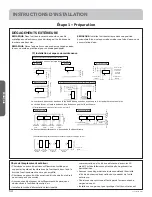
(Connexion standard
des unités intérieures
A,B et C. Aussi
illustration des
connexions d’une
carte de chambre en
option (future) et des
connexions d’une
commande centrale.)
Modèle :
2U20EH2VHA
3U24EH2VHA
4U36MS2HDA1
4U36EH2VHA1
(Connexion standard
des unités intérieures
A et B)
A
B
C
Strain Relief Brackets
Optional
YCZ-A004
Suggested Colors:
L1=White
L2=Black
L3=Red
Ground= Solid Green
or Green-Yellow
Outdoor Unit
Indoor Unit A
Outdoor unit
Power Wiring
3
2
1 )
(N
)
(L
)
(C
2
1 )
(N
)
(L
Indoor unit A
Control Wiring
4 Wire - 14 AWG
Stranded
4
3
To Service Disconnect
1
2
3
=White
=Black
=Red
=Green
A
B
C
D
Sugested Colors
230 Volt Supply. 1 to L1, 2 to L2.
Indoor unit B
Indoor unit C
Indoor unit D
3
2
1 )
(N
)
(L
)
(C
3
2
1 )
(N
)
(L
)
(C
3
2
1 )
(N
)
(L
)
(C
Strain Relief
Brackets
Only on FlexFit 3U & 4U
and Arctic 2U & 3U
Only on FlexFit 4U
and Arctic 2U & 3U
Diagnostic and Control
Câblage d'alimentation
Pour déconnecter le service
Alimentation 208/230 volts. L1 à L1. L2 à L2.
Câblage d'alimentation
Pour déconnecter le service
Alimentation 208/230 volts. L1 à L1. L2 à L2.

