21
OPERATION MANUAL
5.4 BLADE GUIDE ADJUSTMENT
The blade guides are set before the machine leaves the factory but made need to be adjusted
due to movement while shipping, or general wear and tear after long operation.
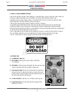
F
ig
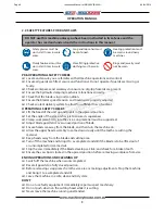
. 5.8
Cap Screws
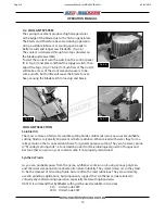
F
ig
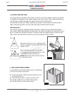
. 5.9
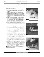
To adjust the support roller
1. DISCONNECT THE BAND-SAW FROM THE POWER SUPPLY
2. Make sure that the blade is oiled and correctly
tensioned.
3. Raise and lock the bow saw for easy access. Slide the
blade guides as close as possible together and lock in
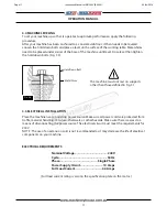
place. Remove the blade guards by loosening the
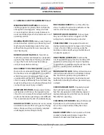
button head screws. (Fig.5.7)
4. Loosen the cap screws (Fig.5.8) and adjust the blade
guide housing so the back of the blade just touches
the bearing, making sure the guide housing is not
tilted.
5. Tighten the cap screws.
NOTE:
To access the cap screws on the other blade guide
you will need to remove the two Phillips head screws and
move the limit switch and its bracket out of the way.
To adjust the side bearings
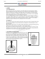
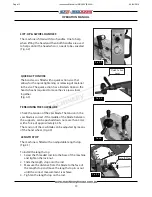
1. Loosen the lock nut on the top of eccentric bolt.
2. Using a spanner on the hex section between the
bearing and the casting, adjust the bearing, so it is
against the side of the blade. There should be no
clearance. (Fig. 5.9)
3. Tighten the lock nut making sure that the eccentric
bolt does not turn.
4. Adjust the other ball bearing guide.
5. Repeat steps 1-4 on the other set of ball bearing guides
on the opposite side of the saw bow.
F
ig
. 5.10
Lock Nut
Hex Section
F
ig
. 5.7
Button Screws
Page 21
Instruction Manual for EB-260V (B062V)
04/04/2019

