13
OPERATION MANUAL
Preparing the Milling Machine for Service
1. Remove any crating which may be covering
the machine on the pallet.
2. Remove from the pallet the toolbox and any
other items shipped separately with the machine.
Inside the toolbox are the fine and coarse feed
handles, along with other tools.
3. Check that the eye bolt on the ram is tight.
4. Check that the lock handles on the ram are
locked tight.
5. Remove the nuts and/or bolts, which secure
the machine to the pallet.
6. Center the overhead lifting device and sling
using the eye bolt.
NOTE:
Be sure that the lifting slings and crane
have the capacity to handle the lift. When lifting
using the eye bolt, the machine will tip forward.
A sling attached to the front of the machine will
help stabilize the machine. Be careful when doing
this, to prevent the sling from damaging any
components on the front of the machine.
7. Lift the machine off the pallet no higher
than necessary, then pull the pallet out of the
way.
DO NOT
put hands or feet underneath the
machine when removing the pallet!
8. Lower the machine over the area where the
machine is to sit and mark where the hold down
bolts are to be set.
NOTE:
Check that the maximum dimensions
of the machine with the table, ram, etc., fully
extended in all possible directions. Be certain to
leave clearance not only for the machine itself,
but also for operating, servicing the machine,
and any unusual sizes of workpieces that might
extend off the machine’s table.
Leveling the Machine
9.
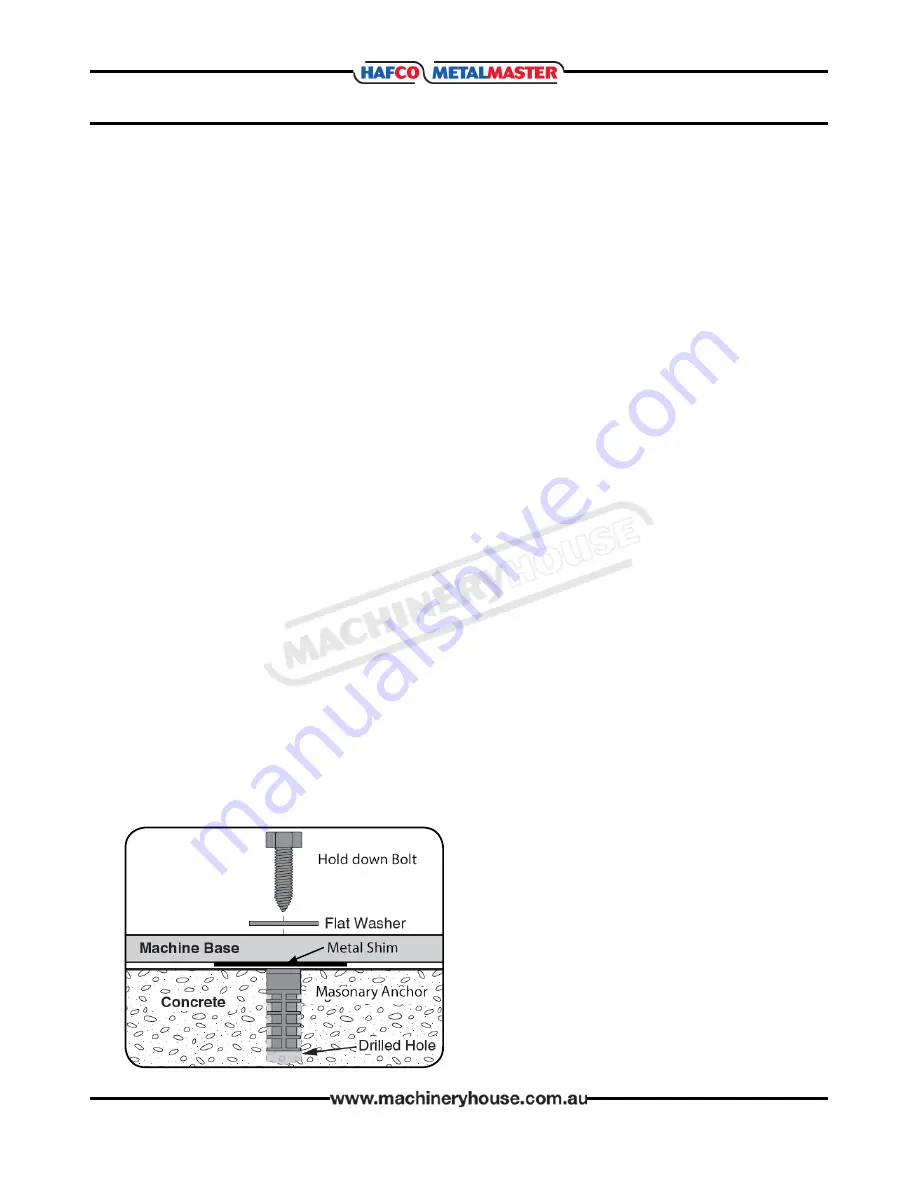
When the machine is over its anchors, level
the machine using shims under the corners that
need them. (Fig. 4) A machinist’s level, placed on
the table should be used for leveling. The table
is the reference surface for both side-to-side and
fore-and-aft leveling. Be certain you get it level in
BOTH directions.
10. When the machine is level, secure the base
with the masonry anchors.
11. Loosen the four hex head nuts that secure
the head to the ram. (about 1/4 turn each, just
enough to allow rotation of the head).
(See adjustments Page 22)
12. While assisting the worm mechanism by
putting upward pressure on the motor by hand,
use the wrench supplied with the machine to
turn the worm nut and raise the head to upright
position.
13. Tighten the headbolts slightly — not
torqued — just snug.
14. Using mineral spirits or other non-flamma-
ble cleaning solvent, clean all of the rust proofing
from where it may have been applied. This is im-
portant as moving the table or any other compo-
nent before removing the rust proofing will only
put rust proofing where you don’t want it.
Some of the following steps may have already
been performed on the machine. If so, ignore the
instructions related to these steps. Otherwise,
perform them in the order listed.
15. Install the table end and cross-feed handles
on their respective shafts using the nuts on the
shafts to secure them.
16. Remove any rust proofing from the drawbar
and its washer, and put the drawbar with washer
installed into the spindle center through the top
of the machine.
17. Slide the fine feed handwheel over the
handwheel hub and push it back until its roll-pin
engages the hole in the hub and the wheel is
flush with the hub surface.
18. Put the coarse feed lever on the feed shaft
and tap it lightly until its roll-pin engages a hole
in the hub and it is flush against the hub surface.
19. Unwrap and clean the knee crank and install
it on its shaft.
SET-UP AND INSTALLATION
Fig. 4
Page 13
Instructions Manual for BM-23A (M595D)
12/02/2018


