20
5.52.131.00.01.09
12.5.1
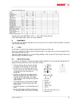
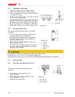
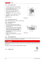
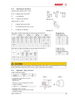
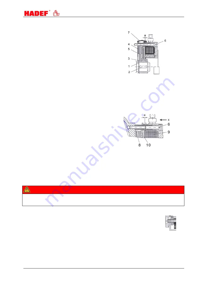
Assembling the brake
1 Insert the retaining ring (1) into the shaft slot.
2 Insert the feather key (2) into the motor shaft.
3 Fix hub (3) with retaining ring (1).
4 Assemble the friction plate (4) if existent.
5 Push the rotor (5) onto the hub (3).
6 Lock the magnet body with the 3 fastening
screws (6).
7 Set air gap “a” (refer to “adjusting the air gap”)
8 Assemble the dust-protection ring (7) if
existent.
9Electric connection
Illustration 14
12.5.2
Disassembly of the brake
Disassembly is performed in reverse order to the assembly.
12.5.3
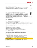
Adjusting the air gap
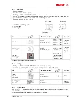
View "X" on the brake.
1 Loosen the locking screws (6) by half a turn.
2 Turn the cap screws (8) into the magnetic body
(9) anti-clockwise.
3 By turning the locking screws (6) clockwise,
move the magnetic body (9) towards the
anchor plate (10) using a feeler gauge until
nominal air gap “a” is reached (see table).
4 Unscrew the cap screws (8) from the magnetic
body clockwise.
5 Tighten the locking screws (6).
6 Check the air gap again and re-adjust if
necessary.
Illustration 15
12.6 Overload
protection
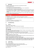
If the hoist does not lift the permitted load, the overload protection must be adjusted. Adjustment may only be
done by a service company, authorised by the manufacturer!
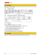
DANGER!
The factory setting of the overload protection is secured by a seal. Any guarantee becomes invalid if this setting is
changed. Should maintenance be necessary, please contact a service company that is authorised by the
manufacturer.
Depending on the type of hoist, the following variants are possible:
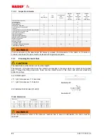
12.6.1 Slipping
clutch
Illustration 16

