Page 47 of 62
Brushless DC Controller HST-350
Orginal
operating
manual
Rev1.3
Mounting and commissioning
4.5 Power control / operating modes
Depending on the application, the HST-350 can be configured for different operating modes. You can set
the desired mode via the GUI (graphical user interface).
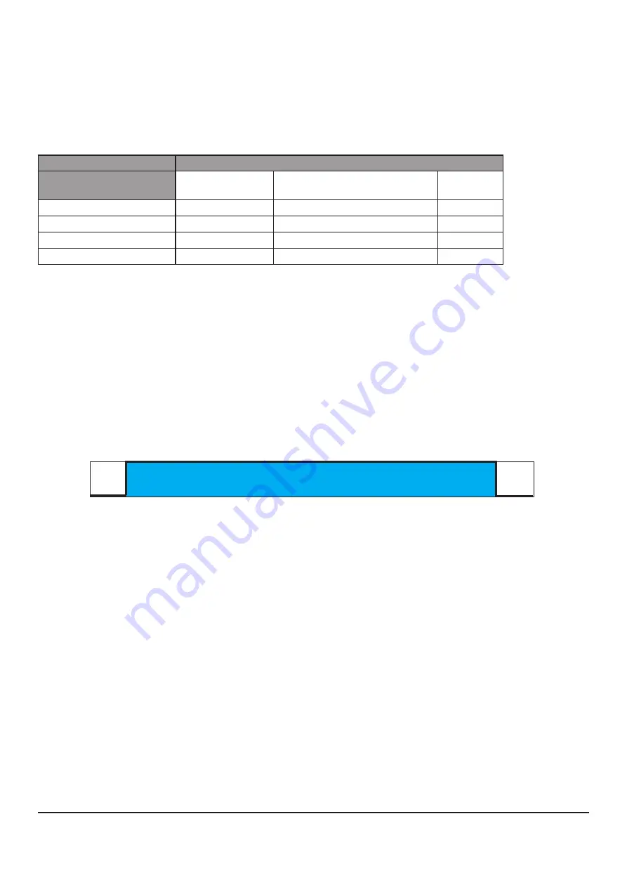
Possible combinations for control and regulation
Regler-Ansteuerung
Operating mode
Motor control
CAN
ADC (Analog Digital Converter) –
„Pedal control“
PPM
PWM Mode
X
X
X
Current control
X
X
X
Speed control
X
X
X
Generator mode
X
Control in the operating modes ADC and PPM
Currently there are several modes available for power control
a.)
‚Pedal control‘ (ADC) with analog input 0 - 5 V (voltage)
• Uses analog inputs PVS_1 and PVS_2 (see table [Pin 15 / 16]).
• This analog voltage can be generated with the potentiometer of an accelerator pedal, which must be
supplied either internally or externally with 5V.
• By default, the controller works with a lower diagnostic distance of 0.5V (0-0.5V) and an upper diagno-
stic distance of 0.5V (4.5V-5V).
• Thereby 0.5V corresponds to „0% power“ and 4.5V to „100% power“.
Working area
0V
0,5V
0% Power
4,5V
100% Power
5V
These data are parameterizable in the Basic-EEPROM.
b.) ‚PPM control‘ ( pulse-pause modulation)
- Uses input signals of the PPM input (see Table 3-2 [Pin 18 / 19], not shown in Fig. 2-1).
The PPM input signal must meet the following (servo PPM, pulse-pause modulation) requirements:
td = 1.0 ms to 2.0 ms :
pulse length (on-time)
fper = 50 Hz to 495 Hz :
duration of the PPM signal
0 V: Low signal during the off-time tper - td
5 V : High signal during pulse length td
Minimum value :
td = 1.0 ms pulse length (-100% = reverse)
Average setting :
td = 1.5 ms pulse width (0% = neutral position, motor off)
Maximum value :
td = 2.0 ms pulse width (+ 100% = forward)


