


4.8 Sensor installation
4.8.1 Sensor positioning
The sensor must be installed in a socket or flow chamber that allows contact with the sample fluid to
be analyzed. The sensor and measuring instrument are connected by a cable. The standard sensor
cable lengths are 3, 5, 10, 15 and 20 meters. Ensure that the sensor will be mounted:
• perpendicular to the pipe
• on a horizontal pipe section (or on flow-ascending vertical pipe)
• minimum of 15 meters away from the pump's discharge side
• in a place where the sample flow is stable and rapid, and as far as possible from:
• valves
• pipe bends
• the suction side of any pumps
• a CO
2
injection system or similar
Note: There may be situations where not all the above conditions can be met. If this is the case, or you have any
concerns, please consult your Hach representative to appraise the situation and define the best applicable solution.
4.8.2 Recommended sample flow rate
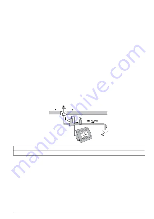
For optimal response time, the recommended sample flow rate for both the K1100 and
M1100 sensors is 150 mL/min. Control the flow with the outlet valve on the flow meter (No. 3 in
) to avoid foam developing inside the flow chamber which could lead to erroneous oxygen
measurement values.
Figure 8 Typical measurement schematic
1
Valve to redirect sample for measurement
3
Flow meter with outlet valve
2
Sensor and flow chamber combination
4
Drain
Section 5 User interface
5.1 Instrument controls
The instrument front panel provides:
• A touch screen acting as display, touch pad and keyboard.
• A LED, showing when the instrument is on.
Turning instrument On and Off
There is no power switch on the instrument. The mains must be disconnected to turn the instrument
off.
Measurement window
The main (numeric) measurement window continuously displays:
English
13
Summary of Contents for ORBISPHERE K-M1100
Page 278: ...2 3 3 1 3 2 278...
Page 279: ...3 3 ESD 3 4 2000 m 6562 ft 2000 m 4 GFCI GFI 279...
Page 280: ...PE 100 240 VAC 5 VDC PE PE 4 1 1 U 2 3 2 4 4 2 1 U 2 3 4 2 5 4 3 280...
Page 281: ...1 3 4 5 6 7 1 2 3 6 4 4 5 4 1 4 6 7 281...
Page 287: ...4 8 4 8 1 3 5 10 15 20 15 2 Hach 4 8 2 1100 1100 150 mL min No 3 8 8 1 3 2 4 5 5 1 LED 287...
Page 288: ...10 1 5 2 5 3 menu Up Main Close Help 5 4 Enter 6 6 1 4 1 Configuration Security ID 288...
Page 301: ...12 2 2 1 2 3 12 2 3 1 2 3 4 301...
Page 330: ...3 3 3 4 2000 6562 2000 4 GFCI GFI 330...
Page 331: ...PE 100 240 5 4 1 1 U 2 3 4 4 2 1 U 2 3 4 5 4 3 331...
Page 332: ...1 3 4 5 6 7 1 2 3 6 4 4 5 4 1 4 6 7 332...
Page 338: ...4 8 4 8 1 3 5 10 15 20 15 CO2 Hach 4 8 2 150 K1100 M1100 3 8 8 1 3 2 4 5 5 1 338...
Page 339: ...10 5 2 5 3 Menu Up Main Close Help 5 4 CAP Enter 6 Security 339...
Page 353: ...12 12 1 Hach 12 2 6 CIP ClO2 12 2 1 Ksv Ksv 350 1 2 3 12 2 2 1 2 3 353...
Page 354: ...12 2 3 1 2 3 4 354...
Page 406: ...K1100 M1100 28 mm x 143 50 x 49 mm 0 74 kg 5 65 x 1 93 in 1 63 lbs 0 7 kg 2 3 3 1 3 2 406...
Page 407: ...3 3 3 4 2000 m 6562 ft 2000 m 4 DC AC GFCI GFI 407...
Page 408: ...100 240 V AC 5 V DC PE 4 1 1 U 2 3 2 4 4 2 1 U 2 3 4 2 5 4 3 408...
Page 409: ...1 3 4 5 6 7 1 2 3 4 4 2 5 4 1 4 6 7 409...
Page 415: ...4 8 4 8 1 3 5 10 15 20 15 CO2 Hach 4 8 2 K1100 M1100 150 mL min 3 8 8 1 3 2 4 5 5 1 LED 415...
Page 416: ...10 5 2 service 5 3 menu Up Main Close Help 5 4 CAP Enter 6 416...
Page 430: ...12 2 2 1 2 3 12 2 3 1 2 3 4 430...
Page 531: ......


