


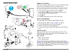
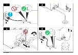


Flush the analyzer
The cleanliness of commercially available tubing is not consistent
(particularly stainless steel). The manufacturer recommends that a clean
cycle is done at initial startup to fully flush the sample inlet tubing. Refer
to
on page 24.
Start automatic analysis
Put the analyzer in Auto TOC mode. Refer to
on page 24.
The analyzer is calibrated at the factory. For accurate results, let the
analyzer complete five analyses before the reported data is accepted as
correct.
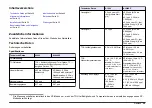
If at any time the sample is not within the analyzer specifications, an
alarm occurs (e.g., "Code 38" or "Code 40"). Refer to and .
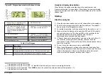
Give the analyzer a channel ID
Each analyzer must have a unique channel ID (1–8) to identify the
analyzer. The channel ID is the network address for the analyzer and
corresponds to a channel LED on the controller. The channel ID is
shown before the analyzer name on the controller display. Duplicate
channel IDs are not permitted on the network.
Note: The controller sets the default channel ID for each analyzer when it first
scans it.
1.
At the controller, select the analyzer, then push
SETUP
.
2.
Use the
UP
and
DOWN
arrows to select System Setup>ID to SN
Xref. The Channel ID–Name is shown for each analyzer connected
to the controller. The first Channel ID is highlighted.
3.
Use the
UP
and
DOWN
arrows to change the channel ID. Push
ENTER
to move the cursor to the next channel ID.
Note: Duplicate channel IDs can be entered while in the edit mode, but they
cannot be saved.
4.
When no more changes are necessary, push
ESC
.
Note: If the controller identifies duplicate channel IDs, the display shows a
message that identifies the condition and that the conflict must be corrected
before the screen can be exited.
5.
Push
ENTER
. The controller resets the network. The main screen is
shown.
Give the controller a network address
Each controller must have a unique network address for identification
and reporting functions (9–16). The default network address of the
controller is 9. It may be necessary to change the network address of the
controller to prevent network conflict.
To change the network address of the controller:
1.
At the controller, push down and hold
SETUP
. Disconnect the power
adapter from the controller, then connect it again. (On an
A1000 S20P or A1000XP, turn the analyzer off and back on.) The
controller display shows the current network (A-Net) address for the
controller.
2.
Use the
UP
and
DOWN
arrows to select the controller network
address (9–16).
3.
Push
ENTER
to save the change.
Set the date and time
Set the date and time on each controller. The controller transmits the
date and time to the analyzers connected to it so that report functions
are in sync.
1.
At the controller, push
SETUP
.
2.
Use the
UP
and
DOWN
arrows to select System Setup>System
Time.
3.
Push
ENTER
. The flashing cursor becomes an underscore.
4.
Use the
UP
and
DOWN
arrows to set the date (dd/mm/yy) and then
the time (hh:mm) in 24-hour format. Push
ENTER
to move the cursor
to the next interval (e.g., the day or year).
Note: Although only the right digit of each interval is highlighted, all of the
interval is selected.
5.
Push
ESC
multiple times to go back to the main screen.
English
23
Summary of Contents for A1000
Page 2: ...English 3 Deutsch 29 Italiano 57 Fran ais 83 Espa ol 110 2...
Page 28: ...28 English...
Page 56: ...56 Deutsch...
Page 82: ...82 Italiano...
Page 109: ...Fran ais 109...
Page 136: ...136 Espa ol...
Page 137: ......


