


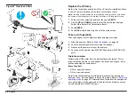


Connect the analog output (optional)
One 0–20 mA or 4–20 mA analog output is available at the 4–20 mA
connector on the I/O connector block. The analog output signal is
proportional to the last TOC reading. The analog output range and its
corresponding TOC zero-scale and full-scale values are the same as the
selected DAC TOC zero-scale and full-scale values. If a critical error
occurs during a TOC analysis, the analog output goes to the selected
DAC error output state.
Connect a current receiving device to the 4–20 mA connector on the I/O
connector block. Refer to
.
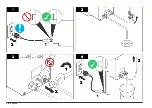
To connect a voltage receiving device instead, convert the analog output
signal to a voltage output with a resistor as shown in
analog output drives resistance between 50 and 500 ohms, including the
interconnecting cables. The precision of the resistor directly affects the
accuracy of the data. A 1% wire-wound resistor or better is
recommended. For maximum data integrity, make sure that the resistor
is installed across the input terminals of the receiving device.
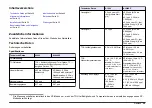
Table 4 Conversion resistors
Resistor
4–20 mA DC voltage range
0–20 mA DC voltage range
50 ohms
0.2–1 VDC
0–1 VDC
250 ohms
1–5 VDC
0–5 VDC
500 ohms
2–10 VDC
0–10 VDC
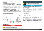
Figure 14 Analog output wiring
1
Current receiving device
4
Voltage receiving device
2
Wiring for a current output signal
5
Conversion resistor
3
Wiring for a voltage output signal
Connect a serial device (optional)
Connect a serial cable to the analyzer and to a serial device (e.g., host
computer) to get the alarm log or all log entries.
Connect the serial cable to the Data Acquisition connector on the I/O
connector block. Refer to
on page 12. A three- or five-conductor serial cable is sufficient for most
serial interfaces, depending on the type of printer. AWG 24 is
recommended.
The Data Acquisition connector is a bidirectional RS232C series
interface, 1200 baud and 8 data bits (1 stop bit, no parity), that lets the
analyzer communicate with serial devices.
Connect the analyzers and controllers
N O T I C E
Do not use standard BNC terminators. Only use passive or active terminators
supplied by the manufacturer.
As many as eight analyzers and eight C80 controllers can be connected
in any configuration to make a number of different A-Net networks.
Note: Individual analyzers and controllers can be connected or disconnected from
the network without disrupting overall network operation.
To make an A-Net network:
16
English
Summary of Contents for A1000
Page 2: ...English 3 Deutsch 29 Italiano 57 Fran ais 83 Espa ol 110 2...
Page 28: ...28 English...
Page 56: ...56 Deutsch...
Page 82: ...82 Italiano...
Page 109: ...Fran ais 109...
Page 136: ...136 Espa ol...
Page 137: ......


