


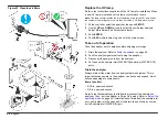

Connect the DAC modules (optional)
Connect two DAC (digital-to-analog conversion) modules to the analyzer
with the two serial cables supplied with the DAC modules (four-
conductor serial cable, AWG 28). The DAC modules transmit the
resistivity and temperature values as 0–20 mA or 4–20 mA outputs.
Remove the serial connectors from the two serial cables. Then, connect
the serial cables to the DAC modules, Diagnostics connector and Bias
connector as shown in
. The DAC modules can be a maximum
of 16.7 m (50 ft) from the analyzer.
For the A1000 S20P and A1000XP, the attached printer is connected to
the Bias connector. Connect the DAC modules to an ex12 VDC
power supply instead of the Bias connector.
The Diagnostics connector is an RS232C series interface, 1200 baud
and 8 data bits (1 stop bit, no parity).
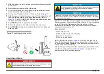
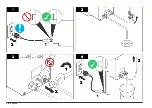
Figure 11 DAC module wiring
1
DAC 1
2
DAC 2
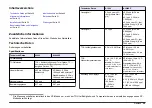
Connect the digital inputs (optional)
Connect a remote device and/or a switch to the Inputs connector on the
I/O connector block. The Inputs connector has two digital inputs. Refer to
The two digital inputs share a common positive terminal. Use an external
5–30 VDC power source or the 12 VDC bias output on the I/O connector
block to supply power to the digital inputs. Refer to
. Each
digital input draws 1–14 mA, depending on the applied voltage. The
digital inputs operate from open collector, open drain or relay outputs.
14
English
Summary of Contents for A1000
Page 2: ...English 3 Deutsch 29 Italiano 57 Fran ais 83 Espa ol 110 2...
Page 28: ...28 English...
Page 56: ...56 Deutsch...
Page 82: ...82 Italiano...
Page 109: ...Fran ais 109...
Page 136: ...136 Espa ol...
Page 137: ......


