background image


284 

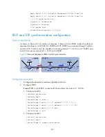
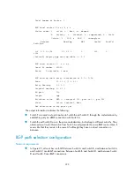
    0.00% packet loss 

    round-trip min/avg/max = 2/2/2 ms 

BGP load balancing configuration   

Network requirements 

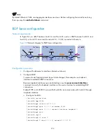
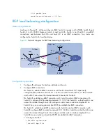
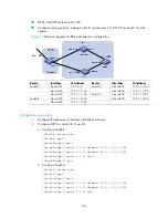
As shown in Figure 91, all the switches run BGP. Switch A resides in AS 65008, Switch B and 

Switch C in AS 65009. Between Switch A and Switch B, Switch A and Switch C are eBGP 

connections, and between Switch B and Switch  C  is  an  iBGP  connection.  Two  routes  are 

configured on Switch A for load balancing. 

Figure 91 

Network diagram for BGP load balancing configuration


Configuration procedure 

1.


Configure IP addresses for interfaces (details not shown). 

2.


Configure BGP connections. 
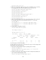
On Switch A, establish eBGP connections with Switch B and Switch C, respectively; 
configure BGP to advertise network 8.1.1.0/24 to Switch B and Switch C, so that Switch B 

and Switch C can access the internal network connected to Switch A.  
On Switch B, establish an eBGP connection with Switch A and an iBGP connection with 
Switch C; configure BGP to advertise network 9.1.1.0/24 to Switch A, so that Switch A can 

access the intranet through Switch B; configure a static route to interface loopback 0 on 

Switch C (or use a routing protocol like OSPF) to establish the iBGP connection.  
On Switch C, establish an eBGP connection with Switch A and an iBGP connection with 
Switch B; configure BGP to advertise network 9.1.1.0/24 to Switch A, so that Switch A can 

access the intranet through Switch C; configure a static route to interface loopback 0 on 
Switch B (or use another protocol like OSPF) to establish the iBGP connection. 

a.


Configure Switch A. 

<SwitchA> system-view 

[SwitchA] bgp 65008 

Summary of Contents for S9500E Series

Page 1: ...H3C S9500E Series Routing Switches Layer3 IP Routing Configuration Guide Hangzhou H3C Technologies Co Ltd http www h3c com Document Version Product Version ...

Page 2: ...zhou H3C Technologies Co Ltd All other trademarks that may be mentioned in this manual are the property of their respective owners Notice The information in this document is subject to change without notice Every effort has been made in the preparation of this document to ensure accuracy of the contents but all statements information and recommendations in this document do not constitute the warra...

Page 3: ...se configuration guides also provide configuration examples to help you apply software features to different network scenarios This preface includes Audience Conventions About the H3C S9500E Documentation Set Obtaining Documentation Documentation Feedback Audience This documentation is intended for Network planners Field technical support and servicing engineers Network administrators working with...

Page 4: ...ose optional syntax choices separated by vertical bars from which you may select multiple choices or none 1 n The argument or keyword and argument combination before the ampersand sign can be entered 1 to n times A line that starts with a pound sign is comments GUI conventions Convention Description Button names are inside angle brackets For example click OK Window names menu items data table and ...

Page 5: ...eneric network device such as a router switch or firewall Represents a routing capable device such as a router or Layer 3 switch Represents a generic switch such as a Layer 2 or Layer 3 switch or a router that supports Layer 2 forwarding and other Layer 2 features ...

Page 6: ...ggable SFP SFP XFP Transceiver Modules Installation Guide Guides you through installing SFP SFP XFP transceiver modules Adjustable Slider Rail Installation Guide Guides you through installing adjustable slider rails to a rack H3C High End Network Products Hot Swappable Module Manual Describes the hot swappable modules available for the H3C high end network products their external views and specifi...

Page 7: ...7 Category Documents Purposes Error code reference Explains the error codes for the QoS module ...

Page 8: ...echnical Documents Provides hardware installation software upgrading and software feature configuration and maintenance documentation Products Solutions Provides information about products and technologies as well as solutions Technical Support Documents Software Download Provides the documentation released with the software version Documentation feedback You can e mail your comments about product...

Page 9: ...24 Displaying and maintaining a routing table 25 Static routing configuration 27 Static route 27 Default route 27 Application environment 27 Configuring a static route 28 Configuring BFD for static routes 29 Configuring static route FRR 31 Displaying and maintaining static routes 32 Static route configuration examples 33 Basic static route configuration example 33 Static route FRR configuration ex...

Page 10: ...e authentication 56 Specifying a RIP neighbor 57 Configuring RIP to MIB binding 57 Configuring the RIP packet sending rate 57 Configuring RIP FRR 58 Configuring BFD for RIP 59 Single hop detection in BFD echo packet mode 59 Bidirectional detection in BFD control packet mode 60 Displaying and maintaining RIP 60 RIP configuration examples 61 Configuring RIP version 61 Configuring RIP route redistrib...

Page 11: ...bound route filtering 112 Configuring ABR Type 3 LSA filtering 112 Configuring an OSPF cost for an interface 113 Configuring the maximum number of OSPF routes 114 Configuring the maximum number of load balanced routes 114 Configuring a priority for OSPF 114 Configuring OSPF route redistribution 115 Advertising a host route 117 Configuring OSPF network optimization 117 Prerequisites 117 Configuring...

Page 12: ...ing OSPF route redistribution 138 Configuring OSPF to advertise a summary route 140 Configuring an OSPF stub area 143 Configuring an OSPF NSSA area 147 Configuring OSPF DR election 149 Configuring OSPF virtual links 154 OSPF Graceful Restart configuration example 156 Configuring route filtering 158 Configuring OSPF FRR 161 Configuring BFD for OSPF 163 Troubleshooting OSPF configuration 165 No OSPF...

Page 13: ...ion 198 Configuring area authentication 198 Configuring routing domain authentication 199 Configuring system ID to host name mappings 199 Configuring a static system ID to host name mapping 200 Configuring dynamic system ID to host name mapping 200 Configuring IS IS GR 201 Configuring IS IS NSR 202 Configuring IS IS FRR 203 Introduction 203 Configure IS IS FRR to automatically calculate a backup n...

Page 14: ...cies 257 Configuring BGP route reception filtering policies 258 Enabling BGP and IGP route synchronization 259 Configuring BGP route dampening 260 Configuring BGP route attributes 260 Tuning and optimizing BGP networks 262 Configuring BGP keepalive interval and holdtime 262 Configuring the interval for sending the same update 263 Configuring BGP soft reset 263 Enabling the BGP ORF capability 265 E...

Page 15: ... 307 Configuring interface policy routing 307 Displaying and maintaining IP unicast policy routing configuration 308 IP unicast policy routing configuration examples 308 Configuring local policy routing based on packet type 308 Configuring interface policy routing based on packet type 311 IPv6 static routing configuration 313 Introduction to IPv6 static routing 313 Features of IPv6 static routes 3...

Page 16: ... OSPFv3 features supported 343 Protocols and standards 343 OSPFv3 configuration tasks 343 Enabling OSPFv3 343 Enabling an OSPFv3 process 344 Configuring OSPFv3 area parameters 344 Configuring an OSPFv3 stub area 344 Configuring an OSPFv3 virtual link 345 Configuring OSPFv3 network types 346 Configuring the OSPFv3 network type for an interface 346 Configuring an NBMA or P2MP neighbor 346 Configurin...

Page 17: ...figuring IPv6 BGP basic functions 377 Specifying an IPv6 BGP peer 378 Injecting a local IPv6 route 378 Configuring a preferred value for routes from a peer or peer group 378 Specifying the source interface for establishing TCP connections 379 Allowing the establishment of a non direct eBGP connection 380 Configuring a description for an IPv6 peer or peer group 380 Disabling session establishment t...

Page 18: ...onfiguration 405 No IPv6 BGP peer relationship established 405 IPv6 unicast policy routing configuration 406 Introduction to IPv6 unicast policy routing 406 Configuring IPv6 unicast policy routing 406 Configuring IPv6 policy 406 Configuring IPv6 local policy routing 408 Configuring IPv6 interface policy routing 408 Displaying and maintaining IPv6 unicast policy routing configuration 409 IPv6 unica...

Page 19: ...routing policy to IPv6 route redistribution 429 Applying a routing policy to filter received BGP routes 431 Troubleshooting routing policy configuration 433 IPv4 routing information filtering failure 433 IPv6 routing information filtering failure 434 Obtaining support for your product 436 Register your product 436 Purchase value added services 436 Troubleshoot online 436 Access software downloads ...

Page 20: ...a link protocols also known as interface routes Static routes Manually configured routes Dynamic routes Routes discovered dynamically by routing protocols Routing table contents A routing table includes the following key items Destination address Destination IP address or destination network Network mask Specifies in company with the destination address the address of the destination network A log...

Page 21: ...es The destination is directly connected to the router Indirect routes The destination is not directly connected to the router To prevent the routing table from getting too large configure a default route All packets that fail to match any entry in the routing table are forwarded through the default route In Figure 1 the IP address on each cloud represents the address of the network Router G is co...

Page 22: ...on Dynamic routing protocols can be classified based on the following standards operational scope routing algorithm destination address type and IP protocol version Operational scope IGPs Work within an autonomous system including RIP OSPF and IS IS EGPs Work between autonomous systems The most popular one is BGP An autonomous system refers to a group of routers that share the same routing policy ...

Page 23: ...a preference The route found by the routing protocol with the highest preference is preferred Table 1 lists some routing protocols and the default priorities for routes found by them Table 1 Routing protocols and routing preferences Routing approach Preference DIRECT 0 OSPF 10 IS IS 15 STATIC 60 RIP 100 OSPF ASE 150 OSPF NSSA 150 IBGP 255 EBGP 255 UNKNOWN 256 The smaller the preference value the h...

Page 24: ...d the main route is selected again to forward packets Route recursion The next hops of some BGP routes except eBGP routes and static routes cannot be directly connected To forward the packets the outgoing interface to reach the next hop must be available Route recursion is used to find the outgoing interface based on the next hop information of the route Link state routing protocols such as OSPF a...

Page 25: ...ing information permitted by an IPv4 prefix list display ip routing table ip prefix ip prefix name verbose Available in any view Step 6 Display routes of a routing protocol display ip routing table protocol protocol inactive verbose Available in any view Step 7 Display statistics about the network routing table or a VPN routing table display ip routing table vpn instance vpn instance name statisti...

Page 26: ...ilable in any view Step 16 Display IPv6 routing information of a routing protocol display ipv6 routing table protocol protocol inactive verbose Available in any view Step 17 Display IPv6 routing statistics display ipv6 routing table statistics Available in any view Step 18 Display IPv6 routing information for an IPv6 address range display ipv6 routing table ipv6 address1 prefix length1 ipv6 addres...

Page 27: ...fault route when it cannot find any matching entries in the routing table If the destination address of a packet fails to match any entry in the routing table the router selects the default route to forward the packet If there is no default route and the destination address of the packet fails to match any entry in the routing table then the packet is discarded and an ICMP packet is sent to the so...

Page 28: ...ing next hop for the output interface Other attributes You can configure different preferences for different static routes so route management policies can be applied more flexibly For example specifying the same preference for different routes to the same destination enables load sharing while specifying different preferences for these routes enables route backup Configuring a static route Prereq...

Page 29: ...o newly created static routes When configuring a description for a static route specify the effect function and purpose of the route for easy classification management and configuration You can flexibly control static routes by configuring tag values and using the tag values in the routing policy If the destination IP address and mask are both configured as 0 0 0 0 with the ip route static command...

Page 30: ...To do Use the command Remarks Step 1 Enter system view system view Step 2 Configure the source address of echo packets bfd echo source ip ip address Required Not configured by default Step 3 Enable BFD echo packet mode for static routes ip route static dest address mask mask length interface type interface number next hop address bfd echo packet preference preference value tag tag value descriptio...

Page 31: ...session is established at only one end when the echo mode is used For the echo and control mode the switch currently does not support BFD detection on tunnel interfaces Configuring static route FRR When a link or a router fails the packets on the path are discarded or a routing loop occurs To avoid such problems enable static route FRR Figure 2 Network diagram for static route FRR Router A Router ...

Page 32: ...have a backup route configured Do not use static route FRR and static route BFD at the same time Displaying and maintaining static routes To do Use the command Remarks Step 1 Display the current configuration information display current configuration Available in any view Step 2 Display the brief information of the IP routing table display ip routing table Step 3 Display the detailed information o...

Page 33: ...interconnection between any two hosts Figure 3 Network diagram for static route configuration Configuration procedure 1 Configuring IP addresses for interfaces details not shown 2 Configuring static routes a Configure a default route on Switch A SwitchA system view SwitchA ip route static 0 0 0 0 0 0 0 0 1 1 4 2 b Configure two static routes on Switch B SwitchB system view SwitchB ip route static ...

Page 34: ...127 0 0 1 InLoop0 127 0 0 1 32 Direct 0 0 127 0 0 1 InLoop0 b Display the Switch B IP routing table SwitchB display ip routing table Routing Tables Public Destinations 10 Routes 10 Destination Mask Proto Pre Cost NextHop Interface 1 1 2 0 24 Static 60 0 1 1 4 1 Vlan500 1 1 3 0 24 Static 60 0 1 1 5 6 Vlan600 1 1 4 0 30 Direct 0 0 1 1 4 2 Vlan500 1 1 4 2 32 Direct 0 0 127 0 0 1 InLoop0 1 1 5 4 30 Di...

Page 35: ...2 1 ms 1 ms 1 ms 1 1 4 1 3 1 ms 1 ms 1 ms 1 1 2 2 Trace complete Static route FRR configuration example Network requirements Figure 4 shows that Switch S Switch A and Switch D are interconnected through static routes When Link A between Switch S and Switch D fails traffic is switched to Link B immediately Figure 4 Network diagram for static route FRR configuration Switch S Switch D Switch A Loop 0...

Page 36: ... Switch S SwitchS bfd echo source ip 1 1 1 1 SwitchS ip ip prefix abc index 10 permit 4 4 4 4 32 SwitchS route policy frr permit node 10 SwitchS route policy if match ip prefix abc SwitchS route policy apply fast reroute backup interface vlan interface 100 backup nexthop 12 12 12 2 SwitchS route policy quit SwitchS ip route static fast reroute route policy frr b Configure Switch D SwitchS bfd echo...

Page 37: ...ve Adv Age 00h01m27s Tag 0 b Display route 1 1 1 1 32 on Switch D and view the backup next hop information SwitchD display ip routing table 1 1 1 1 verbose Routing Table Public Summary Count 2 Destination 1 1 1 1 32 Protocol Static Process ID 0 Preference 60 Cost 0 NextHop 13 13 13 1 Interface vlan 200 BkNextHop 24 24 24 2 BkInterface vlan 101 RelyNextHop 0 0 0 0 Neighbor 0 0 0 0 Tunnel ID 0x0 Lab...

Page 38: ...it Implement BFD through BFD echo packets SwitchA system view SwitchA bfd echo source ip 123 1 1 1 SwitchA interface vlan interface 10 SwitchA vlan interface10 bfd min echo receive interval 300 SwitchA vlan interface10 bfd detect multiplier 7 SwitchA vlan interface10 quit SwitchA ip route static 120 1 1 1 24 vlan interface 10 10 1 1 100 bfd echo packet SwitchA ip route static 120 1 1 1 24 11 1 1 2...

Page 39: ...lan11 a When the link between Switch B and the Layer 2 switch goes down Switch A can quickly detect the changes on Switch B b Execute the display ip routing table protocol static command and you can see Switch A selects Switch D to reach Switch C SwitchA display ip routing table protocol static Public Routing Table Static Summary Count 2 Static Routing table Status Active Summary Count 1 Destinati...

Page 40: ... address 12 1 1 1 24 SwitchA vlan interface12 bfd min transmit interval 500 SwitchA vlan interface12 bfd min receive interval 500 SwitchA vlan interface12 bfd detect multiplier 9 SwitchA vlan interface12 quit SwitchA ip route static 14 1 1 0 24 vlan interface 12 12 1 1 2 bfd control packet SwitchA quit b Configure Switch B SwitchB system view SwitchB interface vlan interface12 SwitchB vlan interfa...

Page 41: ...to Pre Cost NextHop Interface 14 1 1 0 24 Static 60 0 12 1 1 2 Vlan12 Static Routing table Status Inactive Summary Count 0 b When the link between Switch B and Layer 2 switch fails Switch A can detect the failure c Display the static route information on Switch A The static route is inactive SwitchA display ip routing table protocol static Public Routing Table Static Summary Count 1 Static Routing...

Page 42: ...ite which means the destination network is unreachable RIP is not suitable for large scaled networks for this reason RIP prevents routing loops by implementing the split horizon and poison reverse functions RIP routing table A RIP router has a routing table containing routing entries of all reachable destinations and each routing entry contains the following Destination address IP address of a hos...

Page 43: ...ic value of 16 is defined as unreachable When a routing loop occurs the metric value of the route will increment to 16 Split horizon To prevent routing loops and save bandwidth a router does not send routing information back to the neighboring router the information came from Poison reverse A router sets the metric of routes received from a neighbor to 16 unreachable and sends back these routes to...

Page 44: ...ast networks Supports multicast routing update to reduce resource consumption Supports plain text authentication and MD5 authentication to enhance security RIPv2 has two types of message transmission broadcast and multicast Multicast is the default type using 224 0 0 9 as the multicast address The interface working in the RIPv2 broadcast mode can also receive RIPv1 messages RIP message format RIPv...

Page 45: ...ssages include next hop information If set to 0 0 0 0 it indicates that the originator of the route is the best next hop otherwise it indicates a next hop better than the originator of the route RIPv2 authentication RIPv2 sets the AFI field of the first route entry to 0xFFFF to identify authentication information as shown in Figure 9 Figure 9 RIPv2 authentication message Authentication type A valu...

Page 46: ...chable This mechanism cannot detect link faults quickly After BFD is configured for RIP when BFD detects a broken link RIP can quickly age out the unreachable route thus avoiding interference to other services Protocols and standards RFC 1058 Routing Information Protocol RFC 1723 RIP Version 2 Carrying Additional Information RFC 1721 RIP Version 2 Protocol Analysis RFC 1722 RIP Version 2 Protocol ...

Page 47: ... after enabling RIP to validate RIP on a specific interface You can enable RIP on all interfaces using the command network 0 0 0 0 Configuring the interface behavior To do Use the command Remarks Step 1 Enter system view system view Step 2 Enter RIP view rip process id vpn instance vpn instance name Step 3 Disable all interfaces from sending routing updates the interfaces can still receive updates...

Page 48: ...d broadcasts and RIPv2 broadcasts multicasts and unicasts To do Use the command Remarks Step 1 Enter system view system view Step 2 Enter RIP view rip process id vpn instance vpn instance name Step 3 Specify a global RIP version version 1 2 Optional By default if an interface has a RIP version specified the version takes precedence over the global one If no RIP version is specified for an interfac...

Page 49: ...ew Step 2 Enter interface view interface interface type interface number Step 3 Define an inbound additional routing metric rip metricin route policy route policy name value Optional 0 by default Step 4 Define an outbound additional routing metric rip metricout route policy route policy name value Optional 1 by default Configuring RIPv2 route summarization Route summarization means that subnets in...

Page 50: ...y Required Enabled by default Step 4 Return to system view quit Step 5 Enter interface view interface interface type interface number Step 6 Advertise a summary route rip summary address ip address mask mask length Required You must disable RIPv2 route automatic summarization before advertising a summary route on an interface Disabling host route reception RIPv2 can be disabled from receiving host...

Page 51: ...ise a default route to disable an interface of the RIP process from default route advertisement you can use the rip default route no originate command on the interface To do Use the command Remarks Step 1 Enter system view system view Step 2 Enter RIP view rip process id vpn instance vpn instance name Step 3 Enable RIP to advertise a default route default route only originate cost cost Optional No...

Page 52: ...policy acl number ip prefix ip prefix name export protocol process id interface type interface number Required Not configured by default The filter policy import command filters incoming routes Routes not passing the filtering will be neither installed into the routing table nor advertised to neighbors The filter policy export command filters outgoing routes including routes redistributed with the...

Page 53: ...cy route policy name tag tag Required No redistribution is configured by default Only active routes can be redistributed You can use the display ip routing table protocol command to display route state information If equal cost routes are redistributed from a protocol with the import route command an interface will ignore the tags of these routes when advertising them out Configuring RIP network o...

Page 54: ... split horizon and poison reverse If both split horizon and poison reverse are configured only the poison reverse function takes effect The split horizon and poison reverse functions can avoid routing loops Enabling split horizon The split horizon function disables an interface from sending route information back to the neighboring router that was the source of the information This prevents routin...

Page 55: ...se the command Remarks Step 1 Enter system view system view Step 2 Enter RIP view rip process id vpn instance vpn instance name Step 3 Configure the maximum number of load balanced routes maximum load balancing number Optional Eight by default Enabling zero field check on incoming RIPv1 messages Some fields in the RIPv1 message must be zero These fields are called zero fields You can enable zero f...

Page 56: ...o Use the command Remarks Step 1 Enter system view system view Step 2 Enter RIP view rip process id vpn instance vpn instance name Step 3 Enable source IP address check on incoming RIP messages validate source address Optional Enabled by default Disable the source IP address check feature if the RIP neighbor is not directly connected Configuring RIPv2 message authentication In a network requiring ...

Page 57: ...rce address check on incoming RIP updates undo validate source address Required Not disabled by default Do not use the peer ip address command when the neighbor is directly connected because the neighbor may receive both the unicast and multicast or broadcast of the same routing information If a specified neighbor is not directly connected then disable the source address check on incoming updates ...

Page 58: ... for non recursive RIP routes that are learned from direct connected neighbors Do not use RIP FRR and BFD for RIP at the same time otherwise RIP FRR may fail to take effect When the link in the RIP network in Figure 10 fails the packets on the path are discarded or a routing loop occurs until RIP completes routing convergence based on the new network topology In such cases enable RIP FRR to reduce...

Page 59: ... name Required Disabled by default Configuring BFD for RIP For more information about BFD see BFD in the High Availability Configuration Guide BFD for RIP provides the following two link detection modes Single hop detection in BFD echo packet mode for a directly connected neighbor In this mode a BFD session is established only when the neighbor has route information to send Bidirectional detection...

Page 60: ...interface interface type interface number Step 5 Enable BFD on the RIP interface rip bfd enable Required Disabled by default Unidirectional detection in BFD echo packet mode only works for RIP neighbors that are directly connected namely one hop away from each other Using the undo peer command does not remove the neighbor relationship at once therefore it cannot bring down the BFD session all at o...

Page 61: ...ces are down Before configuring these interfaces bring them up using the undo shutdown command Configuring RIP version Network requirements As shown in Figure 11 enable RIPv2 on all interfaces on Switch A and Switch B Figure 11 Network diagram for RIP version configuration Configuration procedure 1 Configure an IP address for each interface details not shown 2 Configure basic RIP functions a Confi...

Page 62: ... version 2 SwitchA rip 1 undo summary b Configure RIPv2 on Switch B SwitchB rip SwitchB rip 1 version 2 SwitchB rip 1 undo summary c Display the RIP routing table on Switch A SwitchA display rip 1 route Route Flags R RIP T TRIP P Permanent A Aging S Suppressed G Garbage collect Peer 192 168 1 2 on Vlan interface100 Destination Mask Nexthop Cost Tag Flags Sec 10 0 0 0 8 192 168 1 2 1 0 RA 50 10 2 1...

Page 63: ... from RIP 100 making the route not advertised to Switch C Figure 12 Network diagram for RIP route redistribution configuration Configuration procedure 1 Configure an IP address for each interface details not shown 2 Configure basic RIP functions a Enable RIP 100 and specify RIP version 2 on Switch A SwitchA system view SwitchA rip 100 SwitchA rip 100 network 10 0 0 0 SwitchA rip 100 network 11 0 0...

Page 64: ...1 InLoop0 127 0 0 0 8 Direct 0 0 127 0 0 1 InLoop0 127 0 0 1 32 Direct 0 0 127 0 0 1 InLoop0 3 Configure route redistribution a On Switch B configure RIP 200 to redistribute direct routes and routes from RIP 100 SwitchB rip 200 SwitchB rip 200 import route rip 100 SwitchB rip 200 import route direct SwitchB rip 200 quit b Display the routing table of Switch C SwitchC display ip routing table Routi...

Page 65: ...n200 12 3 1 0 24 Direct 0 0 12 3 1 2 Vlan200 12 3 1 2 32 Direct 0 0 127 0 0 1 InLoop0 16 4 1 0 24 Direct 0 0 16 4 1 1 Vlan400 16 4 1 1 32 Direct 0 0 127 0 0 1 InLoop0 127 0 0 0 8 Direct 0 0 127 0 0 1 InLoop0 127 0 0 1 32 Direct 0 0 127 0 0 1 InLoop0 Configuring an additional metric for a RIP interface Network requirements RIP is enabled on all the interfaces of Switch A Switch B Switch C Switch D ...

Page 66: ...SwitchB rip 1 undo summary c Configure Switch C SwitchC system view SwitchB rip 1 SwitchC rip 1 network 1 0 0 0 SwitchC rip 1 version 2 SwitchC rip 1 undo summary d Configure Switch D SwitchD system view SwitchD rip 1 SwitchD rip 1 network 1 0 0 0 SwitchD rip 1 version 2 SwitchD rip 1 undo summary e Configure Switch E SwitchE system view SwitchE rip 1 SwitchE rip 1 network 1 0 0 0 SwitchE rip 1 ve...

Page 67: ...witch A SwitchA Vlan interface200 display rip 1 database 1 0 0 0 8 cost 0 ClassfulSumm 1 1 1 0 24 cost 0 nexthop 1 1 1 1 Rip interface 1 1 2 0 24 cost 0 nexthop 1 1 2 1 Rip interface 1 1 3 0 24 cost 1 nexthop 1 1 1 2 1 1 4 0 24 cost 2 nexthop 1 1 1 2 1 1 5 0 24 cost 2 nexthop 1 1 1 2 The display now shows only one RIP route to network 1 1 5 0 24 with the next hop as Switch B 1 1 1 2 and a cost of ...

Page 68: ...0 0 0 0 255 SwitchA ospf 1 area 0 0 0 0 quit b Configure Switch B SwitchB system view SwitchB ospf SwitchB ospf 1 area 0 SwitchB ospf 1 area 0 0 0 0 network 10 1 1 0 0 0 0 255 SwitchB ospf 1 area 0 0 0 0 network 10 6 1 0 0 0 0 255 SwitchB ospf 1 area 0 0 0 0 quit c Configure Switch C SwitchC system view SwitchC ospf SwitchC ospf 1 area 0 SwitchC ospf 1 area 0 0 0 0 network 10 1 1 0 0 0 0 255 Switc...

Page 69: ...ion Mask Proto Pre Cost NextHop Interface 10 1 1 0 24 RIP 100 1 11 3 1 1 Vlan300 10 2 1 0 24 RIP 100 1 11 3 1 1 Vlan300 10 5 1 0 24 RIP 100 1 11 3 1 1 Vlan300 10 6 1 0 24 RIP 100 1 11 3 1 1 Vlan300 11 3 1 0 24 Direct 0 0 11 3 1 2 Vlan300 11 3 1 2 32 Direct 0 0 127 0 0 1 InLoop0 11 4 1 0 24 Direct 0 0 11 4 1 2 Vlan400 11 4 1 2 32 Direct 0 0 127 0 0 1 InLoop0 127 0 0 0 8 Direct 0 0 127 0 0 1 InLoop0...

Page 70: ...2 Vlan int100 12 12 12 1 24 Vlan int200 13 13 13 1 24 Vlan int200 13 13 13 2 24 Vlan int100 12 12 12 2 24 Vlan int101 24 24 24 2 24 Vlan int101 24 24 24 4 24 Loop 0 4 4 4 4 32 Link A Link B Configuration procedure 1 Configure IP addresses of the interfaces on each switch and configure RIPv2 a Follow Figure 15 to configure the IP address and subnet mask of each interface on the switches The configu...

Page 71: ... 1 SwitchD rip 1 fast reroute route policy frr SwitchD rip 1 quit 3 Verify the configuration a Display route 4 4 4 4 32 on Switch S then you can view the backup next hop information SwitchS display ip routing table 4 4 4 4 verbose Routing Table Public Summary Count 1 Destination 4 4 4 4 32 Protocol RIP Process ID 1 Preference 100 Cost 1 NextHop 13 13 13 2 Interface vlan200 BkNextHop 12 12 12 2 BkI...

Page 72: ... Switch C VLAN interface 200 and VLAN interface 300 on Switch B run RIP process 1 Configure a static route and enable static route redistribution into RIP on Switch C Switch A learns the static route sent by Switch C and the outbound interface of the route is the interface connected to the Layer 2 switch When the link between Switch C and the Layer 2 switch fails BFD can quickly detect the link fa...

Page 73: ...1 network 192 168 3 0 SwitchB rip 1 quit c Configure Switch C SwitchC system view SwitchC rip 1 SwitchC rip 1 network 192 168 1 0 SwitchC rip 1 network 192 168 3 0 SwitchC rip 1 import route static SwitchC rip 1 quit 3 Configure BFD parameters a Configure Switch A SwitchA system view SwitchA bfd session init mode active SwitchA bfd echo source ip 11 11 11 11 SwitchA interface vlan interface 100 Sw...

Page 74: ...nterface RelyNextHop 0 0 0 0 Neighbor 192 168 1 2 Tunnel ID 0x0 Label NULL State Active Adv Age 00h00m47s Tag 0 Destination 100 1 1 0 24 Protocol RIP Process ID 2 Preference 100 Cost 2 NextHop 192 168 2 2 Interface vlan interface 200 BkNextHop 0 0 0 0 BkInterface RelyNextHop 0 0 0 0 Neighbor 192 168 2 2 Tunnel ID 0x0 Label NULL State Inactive Adv Age 00h12m50s Tag 0 c When the link between Switch ...

Page 75: ...tic route to Switch C on Switch A and configure a static route to Switch A on Switch C Enable BFD on VLAN interface 100 of Switch A and VLAN interface 200 of Switch C Switch A is connected to Switch C through Switch D VLAN interface 300 on Switch A runs RIP process 2 and VLAN interface 400 on Switch C VLAN interface 300 and VLAN interface 400 on Switch D run RIP process 1 Enable static route redis...

Page 76: ...nable static route redistribution into RIP so Switch A and Switch C have routes to send to each other a Configure Switch A SwitchA rip 1 SwitchA rip 1 network 192 168 1 0 SwitchA rip 1 peer 192 168 2 2 SwitchA rip 1 undo validate source address SwitchA rip 1 import route static SwitchA rip 1 quit SwitchA interface vlan interface 100 SwitchA Vlan interface100 rip bfd enable SwitchA Vlan interface10...

Page 77: ...rface 200 SwitchC Vlan interface200 bfd min transmit interval 500 SwitchC Vlan interface200 bfd min receive interval 500 SwitchC Vlan interface200 bfd detect multiplier 7 SwitchC Vlan interface200 quit 4 Configure static routes a Configure a static route to Switch C on Switch A SwitchA ip route static 192 168 2 0 24 vlan interface 100 192 168 1 2 SwitchA quit b Configure a static route to Switch A...

Page 78: ...ghbor 192 168 3 2 Tunnel ID 0x0 Label NULL State Inactive Adv Age 00h12m50s Tag 0 c When the link between Switch B and Switch C fails Switch A quickly detects the link state change d Display the BFD information of Switch A Switch A deleted the neighbor relationship with Switch C and displays no output information SwitchA display bfd session e Display the RIP routes of RIP process 1 on Switch A The...

Page 79: ...ould be configured on the local end Solution Use the display current configuration command to check RIP configuration Use the display rip command to check whether an interface is disabled Route oscillation occurred Symptom When all links work well route oscillation occurs on the RIP network After displaying the routing table some routes in the routing table may appear and disappear intermittently ...

Page 80: ...S into different areas to facilitate management In addition routing information transmitted between areas is summarized to reduce traffic and routing table sizes ECMP routing Supports multiple equal cost routes to a destination Routing hierarchy Supports a four level routing hierarchy that prioritizes routes into intra area inter area external Type 1 and external Type 2 routes Authentication Suppo...

Page 81: ...SAs of the neighbor are missing from the local LSDBs Then they send an LSR packet to each other requesting the missing LSAs The LSA packet contains the digest of the missing LSAs LSU packet Transmits the needed LSAs to the neighbor LSAck packet Acknowledges received LSU packets It contains the headers of received LSAs a packet can acknowledge multiple LSAs LSA types OSPF sends routing information ...

Page 82: ...cks parameters in the packet If the parameters match its own the router considers the sending router an OSPF neighbor Adjacency Two OSPF neighbors establish an adjacency relationship to synchronize their LSDBs Any two neighbors not exchanging route information will not establish an adjacency OSPF area partition Area partition When a large number of OSPF routers are present on a network LSDBs may b...

Page 83: ...lowing All non backbone areas must maintain connectivity to the backbone area The backbone area itself must maintain connectivity In practice due to physical limitations the requirements may not be satisfied In this case configuring OSPF virtual links is a solution A virtual link is established between two area border routers through a non backbone area and is configured on both ABRs to take effec...

Page 84: ...he routing table size and amount of routing information in this area are reduced significantly You can configure the stub area as a totally stub area where the ABR advertises neither the destinations to other areas nor external routes Stub area configuration is optional and not every area is eligible to be a stub area In general a stub area resides on the border of the AS The ABR in a stub area ge...

Page 85: ...hen these LSAs travel to the NSSA ABR the ABR translates Type 7 LSAs to Type 5 LSAs for advertisement to Area 0 and Area 2 On the left side of Figure 21 RIP routes are translated into Type 5 LSAs by the ASBR of Area 2 and distributed into the OSPF AS However Area 1 is an NSSA area so these Type 5 LSAs cannot travel to Area 1 Like stub areas virtual links cannot transit NSSA areas Figure 21 NSSA ar...

Page 86: ...onnects the backbone area to a non backbone area The connection between an area border router and the backbone area can be physical or logical Backbone router At least one interface of a backbone router must be attached to the backbone area Therefore all ABRs and internal routers in area 0 are backbone routers ASBR A router exchanging routing information with another AS is an ASBR which may not re...

Page 87: ...s upon the link layer protocol into the following types Broadcast When the link layer protocol is Ethernet or FDDI OSPF considers the network type broadcast by default On broadcast networks hello packets LSU packets and LSAck packets are generally sent to multicast addresses such as 224 0 0 5 reserved for OSPF routers and 224 0 0 6 reserved for OSPF DRs while DD packets and LSR packets are unicast...

Page 88: ...on therefore many system and bandwidth resources are consumed The DR was introduced to solve the problem On a network a DR is elected to advertise routing information among other routers If the DR fails routers on the network must elect another DR and synchronize information with the new DR This process is time consuming and prone to routing calculation errors The BDR can solve this problem The BD...

Page 89: ...rather than P2P and P2MP interfaces A DR is an interface of a router and belongs to a single network segment Another interface of the router may be a BDR or DRother If a router with the highest router priority is added after DR and BDR election the router cannot become the DR immediately The DR cannot be the router with the highest priority in a network and the BDR cannot be the router with the se...

Page 90: ...is defined as password information for authentication type 1 and defined as Key ID MD5 authentication data length and sequence number for authentication type 2 MD5 authentication data is added following an OSPF packet rather than contained in the Authentication field Hello packet As shown in Figure 27 a router sends hello packets periodically to neighbors to find and maintain neighbor relationship...

Page 91: ...router DD packet As shown in Figure 28 two routers exchange DD packets describing their LSDBs for database synchronization which are contents in DD packets including the header of each LSA uniquely representing an LSA The LSA header occupies a small part of an LSA to reduce traffic between routers The recipient checks the availability of the LSA using the LSA header Figure 28 DD packet format Vers...

Page 92: ...aster The DD sequence number then increments until the complete database description has been sent LSR packet After exchanging DD packets any two routers know which LSAs of the peer routers are missing from the local LSDBs In this case they send LSR packets requesting the missing LSAs The packets contain the brief of the missing LSAs Figure 29 LSR packet format Major fields of the LSR packets are ...

Page 93: ... Number of LSAs LSA 0 7 15 31 LSA LSAck packet LSAck packets are used to acknowledge received LSU packets by carrying LSA headers to describe corresponding LSAs Multiple LSAs can be acknowledged in a single LSAck packet Figure 31 LSAck packet format LSA header format All LSAs have the same header as shown in Figure 32 ...

Page 94: ...n transmission LS type Type of the LSA Link state ID The contents of this field depend on the LSA s type Advertising router ID of the router that originates the LSA LS sequence number Used by other routers to judge new and old LSAs LS checksum Checksum of the LSA except for the LS age field Length Length in bytes of the LSA including the LSA header Formats of LSAs Router LSA Figure 33 Router LSA f...

Page 95: ...es a link to a transit network a value of 3 indicates a link to a stub network and a value of 4 indicates a virtual link TOS Number of different TOS metrics given for this link Metric Cost of using this router link TOS IP Type of Service that this metric refers to TOS metric TOS specific metric information Network LSA A Network LSA as shown in Figure 34 is originated by the DR on a broadcast or NB...

Page 96: ... For a Type 3 LSA it is an IP address outside the area for a Type 4 LSA it is the router ID of an ASBR outside the area Network mask The network mask for the Type 3 LSA set to 0 0 0 0 for the Type 4 LSA Metric The metric to the destination A Type 3 LSA can be used to advertise a default route if the Link state ID and Network mask are set to 0 0 0 0 AS external LSA An AS external LSA as shown in Fi...

Page 97: ...c value which is set to 1 for type 2 external routes and set to 0 for type 1 external routes See Route types for a description of external route types Metric The metric to the destination Forwarding address Data traffic for the advertised destination is forwarded to this address External route tag A tag attached to each external route This is not used by the OSPF protocol It may be used to manage ...

Page 98: ...R Helpers notifying them of a GR Figure 38 Grace LSA format The major field of the Grace LSA is as follows TLVs The defined TLV information includes the length of the grace period with Type value 1 the reason for the GR with Type value 2 and the IP interface address of the restarting router with Type value 3 Figure 39 TLV format ...

Page 99: ...ration of OSPF OSPF backs up the following information All OSPF data to the SMB OSPF must recover normal operation immediately upon the AMB failure Only the OSPF configuration information After active or standby switchover OSPF performs GR to synchronize the LSDB with neighbors The GR feature is mainly used for HA and does not interfere with any other routers When a router shuts down its neighbors...

Page 100: ...esource optimization and allocation flow classification and indication of network bandwidth consumption of each flow in a link TE is implemented on the classified type thin granularity summarization type rather than the summarized type thick granularity summarization type to improve performance and bandwidth utilization To support DS TE application in MPLS OSPF supports Local Overbooking Multiplie...

Page 101: ...his information to originate a Type 3 summary LSA as an inter area route between the PE and CE If a router connects to a PE router in the same area and establishes an internal route backdoor route to a destination in this case because an OSPF intra area route has a higher priority than a backbone route VPN traffic will always travel on the backdoor route rather than the backbone route To avoid thi...

Page 102: ...ce s IP address resides on a network segment of an area the interface belongs to the area and is enabled with OSPF and OSPF advertises the direct route of the interface To run OSPF a router must have a Router ID which is the unique identifier of the router in the AS Following is additional information about Router IDs You can specify a Router ID when creating the OSPF process Any two routers in an...

Page 103: ...card mask Required Not configured by default A network segment can only belong to one area H3C recommends configuring a description for each OSPF process to help identify purposes of processes and for ease of management and memorization H3C recommends configuring a description for each area to help identify purposes of areas and for ease of management and memorization Configuring OSPF areas After ...

Page 104: ...l be sent to the ABR for forwarding To do Use the command Remarks Step 1 Enter system view system view Step 2 Enter OSPF view ospf process id router id router id vpn instance instance name Step 3 Enter area view area area id Step 4 Configure the area as a stub area stub no summary Required Not configured by default Step 5 Specify a cost for the default route advertised to the stub area default cos...

Page 105: ... Defaults to 1 You must use the nssa command on all the routers attached to an NSSA area Using the default cost command only takes effect on the ABR ASBR of an NSSA area Configuring a virtual link Non backbone areas exchange routing information via the backbone area Therefore connectivity between the backbone and non backbone areas and within the backbone itself must be maintained If necessary phy...

Page 106: ...by default The following are examples of how you can change the network type of an interface as needed When an NBMA network becomes fully meshed through address mapping namely when any two routers in the network have a direct virtual link in between you can change the network type to broadcast without manually configuring the neighbors When some routers in the broadcast network do not support mult...

Page 107: ... of an interface as NBMA you must make some special configurations Because NBMA interfaces cannot find neighbors via broadcasting hello packets you must specify neighbors and neighbor DR priorities A DR priority of 0 means the router does not have the DR election right a DR priority greater than 0 means the router has the DR election right To do Use the command Remarks Step 1 Enter system view sys...

Page 108: ...whether a neighbor has the election right or not If you configure the DR priority for a neighbor as 0 then the local router will consider the neighbor has no election right therefore no hello packet is sent to this neighbor reducing the number of hello packets for DR BDR election on networks However if the local router is the DR or BDR it sends hello packets to the neighbor with priority 0 for adj...

Page 109: ...interface Step 4 Return to system view quit Step 5 Enter OSPF view ospf process id router id router id vpn instance instance name Step 6 Specify a neighbor and its DR priority on a P2MP unicast network peer ip address cost value dr priority dr priority Required if the interface type is P2MP unicast Configuring the OSPF network type for an interface as P2P To do Use the command Remarks Step 1 Enter...

Page 110: ...uting tables on routers will be reduced improving the calculation speed of routers Assume in an area are three internal routes 19 1 1 0 24 19 1 2 0 24 and 19 1 3 0 24 By configuring route summarization on the ABR the three routes are summarized into the route 19 1 0 0 16 that is advertised into other areas Configuring route summarization on an ABR If contiguous network segments are available in th...

Page 111: ...s only the summary route in an ASE LSA instead of more specific routes which reduces the number of LSAs in the LSDBs If summarization for redistributed routes is configured on an ASBR it will summarize redistributed Type 5 LSAs that fall into the specified address range If in an NSSA area it also summarizes Type 7 LSAs that fall into the specified address range If this feature is configured on a r...

Page 112: ...outing information with a routing policy specified by the route policy keyword To do Use the command Remarks Step 1 Enter system view system view Step 2 Enter OSPF view ospf process id router id router id vpn instance instance name Step 3 Configure inbound route filtering filter policy acl number gateway ip prefix name gateway ip prefix name ip prefix ip prefix name gateway ip prefix name route po...

Page 113: ...the calculated cost is less than 1 the value of 1 is used If the cost value is not configured for an interface OSPF computes the interface cost automatically To do Use the command Remarks Step 1 Enter system view system view Step 2 Enter interface view interface interface type interface number Step 3 Configure an OSPF cost for the interface ospf cost value Optional By default an interface computes...

Page 114: ...If several routes with the same cost to the same destination are available configuring them as load balanced routes can improve link utilization To do Use the command Remarks Step 1 Enter system view system view Step 2 Enter OSPF view ospf process id router id router id vpn instance instance name Step 3 Configure the maximum number of equivalent load balanced routes maximum load balancing maximum ...

Page 115: ...irect routes and advertise these routes in Type 5 LSAs or Type 7 LSAs By filtering redistributed routes OSPF translates only routes not filtered out into Type 5 LSAs or Type 7 LSAs for advertisement To do Use the command Remarks Step 1 Enter system view system view Step 2 Enter OSPF view ospf process id router id router id vpn instance instance name Step 3 Configure OSPF to redistribute routes fro...

Page 116: ...only to VPN and the default route is redistributed in a Type 3 LSA The PE router will advertise the default route to the CE router Configure the default parameters for redistributed routes You can configure default parameters such as the cost upper limit tag and type for redistributed routes Tags are used to indicate information related to protocols For example when redistributing BGP routes OSPF ...

Page 117: ...urity requirements of some mission critical networks Configure OSPF network management functions such as binding OSPF MIB with a process sending trap information and collecting log information Prerequisites IP addresses for interfaces OSPF basic functions Configuring OSPF packet timers You can configure the following timers on OSPF interfaces as needed Hello timer Interval for sending hello packet...

Page 118: ... seconds on P2MP and NBMA interfaces Step 6 Specify the retransmission interval ospf timer retransmit interval Optional The retransmission interval defaults to five seconds The hello and dead intervals restore to default values after you change the network type for an interface The dead interval should be at least four times the hello interval on an interface The poll interval is at least four tim...

Page 119: ... OSPF view ospf process id router id router id vpn instance instance name Step 3 Specify SPF calculation intervals spf schedule interval maximum interval minimum interval incremental interval Optional By default the interval is five seconds With this task configured when network changes are not frequent SPF calculation applies at the minimum interval If network changes become frequent then the SPF...

Page 120: ...command Specifying the LSA generation interval With this feature configured you can protect network resources and routers from being over consumed by frequent network changes To do Use the command Remarks Enter system view system view Enter OSPF view ospf process id router id router id vpn instance instance name Required Configure the LSA generation interval lsa generation interval maximum interva...

Page 121: ...rather than interfaces associated with other processes After an OSPF interface is set to silent other interfaces on the router can advertise direct routes of the interface in Router LSAs but no OSPF packet can be advertised for the interface to find a neighbor This configuration can enhance adaptability of OSPF networking and reduce resource consumption Configuring stub routers A stub router is us...

Page 122: ...must configure the same area authentication mode on all the routers in the area In addition the authentication mode and password for all interfaces attached to the same area must be identical To do Use the command Remarks Step 1 Enter system view system view Step 2 Enter OSPF view ospf process id router id router id vpn instance instance name Step 3 Enter area view area area id Step 4 Configure th...

Page 123: ...emarks Step 1 Enter system view system view Step 2 Enter interface view interface interface type interface number Step 3 Enable OSPF to add the interface MTU into DD packets ospf mtu enable Optional Not enabled by default that is the interface fills in a value of 0 Configuring the maximum number of external LSAs in LSDB To do Use the command Remarks Step 1 Enter system view system view Step 2 Ente...

Page 124: ...name Required Step 3 Make RFC1583 compatible rfc1583 compatible Optional Compatible by default To avoid routing loops H3C recommends that you configure all the routers to be either compatible or incompatible with the external route selection rules defined in RFC1583 Logging neighbor state changes To do Use the command Remarks Step 1 Enter system view system view Step 2 Enter OSPF view ospf process...

Page 125: ...an OSPF process ospf mib binding process id Optional The OSPF process with the smallest process id is bound with OSPF MIB by default Step 3 Enable OSPF trap generation snmp agent trap enable ospf process id ifauthfail ifcfgerror ifrxbadpkt ifstatechange iftxretransmit lsdbapproachoverflow lsdboverflow maxagelsa nbrstatechange originatelsa vifcfgerror virifauthfail virifrxbadpkt virifstatechange vi...

Page 126: ...le neighboring routers and the routing table size is big the router must receive and process large numbers of packets Configuring OSPF to give priority to receiving and processing hello packets helps ensure stable neighbor relationships To do Use the command Remarks Step 1 Enter system view system view Step 2 Configure OSPF to give priority to receiving and processing hello packets ospf packet pro...

Page 127: ...N in the MPLS Command Reference enable traffic adjustment and enable traffic adjustment advertise MPLS TE in the MPLS Command Reference Introduction When a link or a router in the OSPF network fails the packets on the path may be discarded or a routing loop may occur The traffic will be interrupted until OSPF completes routing convergence based on the new network topology In such cases you can ena...

Page 128: ... address Required Not configured by default Step 3 Enter OSPF view ospf process id router id router id vpn instance instance name Step 4 Enable OSPF FRR to automatically calculate a backup next hop fast reroute auto abr only Required Not configured by default Configure OSPF FRR to designate a backup next hop using a routing policy You can use the apply fast reroute backup interface command to spec...

Page 129: ...F and enter its view ospf process id router id router id vpn instance instance name Step 3 Enable opaque LSA advertisement capability opaque capability enable Required Disabled by default Step 4 Enable the IETF standard Graceful Restart capability for OSPF graceful restart ietf Required Disabled by default Step 5 Configure the Graceful Restart interval for OSPF graceful restart interval timer Opti...

Page 130: ...econds by default Configuring the OSPF GR Helper Configuring the IETF standard OSPF GR Helper To do Use the command Remarks Step 1 Enter system view system view Step 2 Enable OSPF and enter its view ospf process id router id router id vpn instance instance name Step 3 Enable opaque LSA reception and advertisement opaque capability enable Required Not enabled by default Step 4 Configure the neighbo...

Page 131: ...ul Restart Performing active or standby switchover on a switch or performing the following configuration on an OSPF router will trigger OSPF Graceful Restart For the IETF standard GR capable routers ensure they have the following capabilities enabled Opaque LSA advertisement IETF standard GR For the non IETF standard GR capable routers ensure they have the following capabilities enabled Link local...

Page 132: ...ss and enter its view ospf process id router id router id vpn instance instance name Step 3 Specify a network to enable OSPF on the interface attached to the network network ip address wildcard mask Step 4 Exit to system view quit Step 5 Enter interface view interface interface type interface number Step 6 Enable BFD on the interface ospf bfd enable Required Not enabled by default One network segm...

Page 133: ...s id nexthop Step 7 Display routing table information display ospf process id routing interface interface type interface number nexthop nexthop address Step 8 Display virtual link information display ospf process id vlink Step 9 Display OSPF request queue information display ospf process id request queue interface type interface number neighbor id Step 10 Display OSPF retransmission queue informat...

Page 134: ... for OSPF configuration By default Ethernet VLAN and aggregate interfaces are down Before configuring these interfaces bring them up using the undo shutdown command Configuring OSPF basic functions Network requirements As shown in Figure 41 all switches run OSPF The AS is split into three areas where Switch A and Switch B act as ABRs to forward routing information between areas After configuration...

Page 135: ... quit SwitchB ospf 1 area 2 SwitchB ospf 1 area 0 0 0 2 network 10 3 1 0 0 0 0 255 SwitchB ospf 1 area 0 0 0 2 quit SwitchB ospf 1 quit c Configure Switch C SwitchC system view SwitchC ospf SwitchC ospf 1 area 1 SwitchC ospf 1 area 0 0 0 1 network 10 2 1 0 0 0 0 255 SwitchC ospf 1 area 0 0 0 1 network 10 4 1 0 0 0 0 255 SwitchC ospf 1 area 0 0 0 1 quit SwitchC ospf 1 quit d Configure Switch D Swit...

Page 136: ...face200 s neighbors Router ID 10 4 1 1 Address 10 2 1 2 GR State Normal State Full Mode Nbr is Master Priority 1 DR 10 2 1 1 BDR 10 2 1 2 MTU 0 Dead timer due in 32 sec Neighbor is up for 06 03 12 Authentication Sequence 0 Neighbor state change count 5 b Display OSPF routing information on Switch A SwitchA display ospf routing OSPF Process 1 with Router ID 10 2 1 1 Routing Tables Routing for Netwo...

Page 137: ...00010 0 Sum Net 10 5 1 0 10 3 1 1 780 28 80000003 12 Sum Net 10 2 1 0 10 2 1 1 1069 28 8000000F 10 Sum Net 10 3 1 0 10 3 1 1 780 28 80000014 2 Sum Net 10 4 1 0 10 2 1 1 769 28 8000000F 13 Area 0 0 0 1 Type LinkState ID AdvRouter Age Len Sequence Metric Router 10 2 1 1 10 2 1 1 769 36 80000012 0 Router 10 4 1 1 10 4 1 1 1663 48 80000012 0 Network 10 2 1 1 10 2 1 1 769 32 80000010 0 Sum Net 10 5 1 0...

Page 138: ...ddress 10 4 1 1 to check connectivity SwitchD ping 10 4 1 1 PING 10 4 1 1 56 data bytes press CTRL_C to break Request time out Reply from 10 4 1 1 bytes 56 Sequence 2 ttl 253 time 15 ms Reply from 10 4 1 1 bytes 56 Sequence 3 ttl 253 time 1 ms Reply from 10 4 1 1 bytes 56 Sequence 4 ttl 253 time 16 ms Reply from 10 4 1 1 bytes 56 Sequence 5 ttl 253 time 1 ms 10 4 1 1 ping statistics 5 packet s tra...

Page 139: ...e a static route destined for network 3 1 2 0 24 SwitchC system view SwitchC ip route static 3 1 2 1 24 10 4 1 2 b On Switch C configure OSPF to redistribute static routes SwitchC ospf 1 SwitchC ospf 1 import route static 4 Verify the configuration a Display the ABR ASBR information of Switch D SwitchD display ospf abr asbr OSPF Process 1 with Router ID 10 5 1 1 Routing Table to ABR and ASBR Type ...

Page 140: ... Destination Cost Type Tag NextHop AdvRouter 3 1 2 0 24 1 Type2 1 10 3 1 1 10 4 1 1 Total Nets 6 Intra Area 2 Inter Area 3 ASE 1 NSSA 0 Configuring OSPF to advertise a summary route Network requirements Configure OSPF on Switch A and Switch B in AS 200 Configure OSPF on Switch C Switch D and Switch E in AS 100 Configure an eBGP connection between Switch B and Switch C Configure Switch C to redistr...

Page 141: ... SwitchA ospf 1 area 0 0 0 0 network 11 2 1 0 0 0 0 255 SwitchA ospf 1 area 0 0 0 0 quit SwitchA ospf 1 quit b Configure Switch B SwitchB system view SwitchB ospf SwitchB ospf 1 area 0 SwitchB ospf 1 area 0 0 0 0 network 11 2 1 0 0 0 0 255 SwitchB ospf 1 area 0 0 0 0 quit c Configure Switch C SwitchC system view SwitchC ospf SwitchC ospf 1 area 0 SwitchC ospf 1 area 0 0 0 0 network 10 1 1 0 0 0 0 ...

Page 142: ...rk 10 4 1 0 0 0 0 255 SwitchE ospf 1 area 0 0 0 0 quit SwitchE ospf 1 quit 3 Configure BGP a Configure Switch B SwitchB system view SwitchB bgp 200 SwitchB bgp peer 11 1 1 2 as 100 SwitchB bgp quit b Configure Switch C SwitchC system view SwitchC bgp 100 SwitchC bgp peer 11 1 1 1 as 200 SwitchC bgp import route ospf 4 Configure route redistribution on Switch B a Configure OSPF to redistribute rout...

Page 143: ...splay ip routing table Routing Tables Public Destinations 5 Routes 5 Destination Mask Proto Pre Cost NextHop Interface 10 0 0 0 8 O_ASE 150 2 11 2 1 1 Vlan100 11 2 1 0 24 Direct 0 0 11 2 1 2 Vlan100 11 2 1 2 32 Direct 0 0 127 0 0 1 InLoop0 127 0 0 0 8 Direct 0 0 127 0 0 1 InLoop0 127 0 0 1 32 Direct 0 0 127 0 0 1 InLoop0 Configuring an OSPF stub area Network requirements Figure 44 shows an AS spli...

Page 144: ...ctions 3 Configure Switch D to redistribute static routes SwitchD ip route static 3 1 2 1 24 10 5 1 2 SwitchD ospf SwitchD ospf 1 import route static SwitchD ospf 1 quit a Display ABR ASBR information on Switch C SwitchC display ospf abr asbr OSPF Process 1 with Router ID 10 4 1 1 Routing Table to ABR and ASBR Type Destination Area Cost Nexthop RtType Intra 10 2 1 1 0 0 0 1 3 10 2 1 1 ABR Inter 10...

Page 145: ...0 In the previous configuration procedure output because Switch C resides in a normal OSPF area its routing table contains an external route 4 Configure Area 1 as a stub area a Configure Switch A SwitchA ospf SwitchA ospf 1 area 1 SwitchA ospf 1 area 0 0 0 1 stub SwitchA ospf 1 area 0 0 0 1 quit SwitchA ospf 1 quit b Configure Switch C SwitchC ospf SwitchC ospf 1 area 1 SwitchC ospf 1 area 0 0 0 1...

Page 146: ... 0 NSSA 0 When Switch C resides in the stub area a default route takes the place of the external route d Filter Type 3 LSAs out of the stub area SwitchA ospf SwitchA ospf 1 area 1 SwitchA ospf 1 area 0 0 0 1 stub no summary SwitchA ospf 1 area 0 0 0 1 quit e Display OSPF routing information on Switch C SwitchC display ospf routing OSPF Process 1 with Router ID 10 4 1 1 Routing Tables Routing for N...

Page 147: ...ween areas You must configure Area 1 as an NSSA area and configure Router C as the ASBR to redistribute static routes into the AS Figure 45 Network diagram for OSPF NSSA area configuration Configuration procedure 1 Configure IP addresses for interfaces details not shown 2 Configure OSPF basic functions see Configuring OSPF basic functions 3 Configure Area 1 as an NSSA area a Configure Switch A Swi...

Page 148: ...1 with Router ID 10 4 1 1 Routing Tables Routing for Network Destination Cost Type NextHop AdvRouter Area 0 0 0 0 0 65536 Inter 10 2 1 1 10 2 1 1 0 0 0 1 10 2 1 0 24 65535 Transit 10 2 1 2 10 4 1 1 0 0 0 1 10 4 1 0 24 3 Stub 10 4 1 1 10 4 1 1 0 0 0 1 Total Nets 3 Intra Area 2 Inter Area 1 ASE 0 NSSA 0 4 Configure Switch C to redistribute static routes SwitchC ip route static 3 1 3 1 24 11 1 1 1 Sw...

Page 149: ...0 2 Routing for ASEs Destination Cost Type Tag NextHop AdvRouter 3 1 3 0 24 1 Type2 1 10 3 1 1 10 2 1 1 Total Nets 6 Intra Area 2 Inter Area 3 ASE 1 NSSA 0 On Switch D you can see an external route imported from the NSSA area Configuring OSPF DR election Network requirements In Figure 46 OSPF Switches A B C and D reside on the same network segment You must configure Switch A as the DR and configur...

Page 150: ...1 area 0 SwitchB ospf 1 area 0 0 0 0 network 192 168 1 0 0 0 0 255 SwitchB ospf 1 area 0 0 0 0 quit SwitchB ospf 1 quit c Configure Switch C SwitchC system view SwitchC router id 3 3 3 3 SwitchC ospf SwitchC ospf 1 area 0 SwitchC ospf 1 area 0 0 0 0 network 192 168 1 0 0 0 0 255 SwitchC ospf 1 area 0 0 0 0 quit SwitchC ospf 1 quit d Configure Switch D SwitchD system view SwitchD router id 4 4 4 4 ...

Page 151: ...Router ID 4 4 4 4 Address 192 168 1 4 GR State Normal State Full Mode Nbr is Master Priority 1 DR 192 168 1 4 BDR 192 168 1 3 MTU 0 Dead timer due in 31 sec Neighbor is up for 00 01 28 Authentication Sequence 0 Switch D becomes the DR and Switch C is the BDR 3 Configure router priorities on interfaces a Configure Switch A SwitchA interface vlan interface 1 SwitchA Vlan interface1 ospf dr priority ...

Page 152: ... BDR 192 168 1 3 MTU 0 Dead timer due in 35 sec Neighbor is up for 00 11 19 Authentication Sequence 0 Router ID 3 3 3 3 Address 192 168 1 3 GR State Normal State Full Mode Nbr is Subordinate Priority 2 DR 192 168 1 4 BDR 192 168 1 3 MTU 0 Dead timer due in 33 sec Neighbor is up for 00 11 15 Authentication Sequence 0 The DR and BDR have no change In the previous configuration procedure output the p...

Page 153: ... Normal State Full Mode Nbr is Subordinate Priority 2 DR 192 168 1 1 BDR 192 168 1 3 MTU 0 Dead timer due in 39 sec Neighbor is up for 00 01 41 Authentication Sequence 0 Switch A becomes the DR and Switch C is the BDR If the neighbor state is full then Switch D has established the adjacency with the neighbor If the neighbor state is 2 way the two switches are neither the DR nor the BDR and they do...

Page 154: ...acts as the Transit Area to connect Area 2 to Area 0 via a configured virtual link between Switch B and Switch C After configuration Switch B can learn routes to Area 2 Figure 47 Network diagram for OSPF virtual link configuration Configuration procedure 1 Configure IP addresses for interfaces details not shown 2 Configure OSPF basic functions a Configure Switch A SwitchA system view SwitchA ospf ...

Page 155: ...f 1 area 0 0 0 2 network 10 3 1 0 0 0 0 255 SwitchC ospf 1 area 0 0 0 2 quit d Configure Switch D SwitchD system view SwitchD ospf 1 router id 4 4 4 4 SwitchD ospf 1 area 2 SwitchD ospf 1 area 0 0 0 2 network 10 3 1 0 0 0 0 255 SwitchD ospf 1 area 0 0 0 2 quit e Display the OSPF routing table of Switch B SwitchB display ospf routing OSPF Process 1 with Router ID 2 2 2 2 Routing Tables Routing for ...

Page 156: ...or Network Destination Cost Type NextHop AdvRouter Area 10 2 1 0 24 2 Transit 10 2 1 1 3 3 3 3 0 0 0 1 10 3 1 0 24 5 Inter 10 2 1 2 3 3 3 3 0 0 0 0 10 1 1 0 24 2 Transit 10 1 1 2 2 2 2 2 0 0 0 0 Total Nets 3 Intra Area 2 Inter Area 1 ASE 0 NSSA 0 Switch B has learned the route 10 3 1 0 24 to Area 2 OSPF Graceful Restart configuration example Network requirements Switch A Switch B and Switch C that...

Page 157: ...ignaling SwitchA ospf 100 enable out of band resynchronization SwitchA ospf 100 graceful restart SwitchA ospf 100 area 0 SwitchA ospf 100 area 0 0 0 0 network 192 1 1 0 0 0 0 255 SwitchA ospf 100 area 0 0 0 0 return b Configure Switch B SwitchB system view SwitchB acl number 2000 SwitchB acl basic 2000 rule 10 permit source 192 1 1 1 0 0 0 0 SwitchB acl basic 2000 quit SwitchB router id 2 2 2 2 Sw...

Page 158: ...o three areas Switch A and Switch B work as ABRs Configure Switch C as an ASBR to redistribute external routes static routes and configure a filter policy on Switch C to filter out redistributed route 3 1 3 0 24 Configure a routing policy on Switch A to filter route 10 5 1 0 24 Figure 49 Network diagram for OSPF route filtering configuration Configuration procedure 1 Configure IP addresses for int...

Page 159: ...200 10 1 1 1 32 Direct 0 0 127 0 0 1 InLoop0 10 2 1 0 24 Direct 0 0 10 2 1 1 Vlan200 10 2 1 1 32 Direct 0 0 127 0 0 1 InLoop0 10 3 1 0 24 OSPF 10 4 10 1 1 2 Vlan100 10 4 1 0 24 OSPF 10 13 10 2 1 2 Vlan200 10 5 1 0 24 OSPF 10 14 10 1 1 2 Vlan100 127 0 0 0 8 Direct 0 0 127 0 0 1 InLoop0 127 0 0 1 32 Direct 0 0 127 0 0 1 InLoop0 4 On Switch C filter out route 3 1 3 0 24 a Configure the IPv4 prefix li...

Page 160: ...5 1 1 24 a Configure the ACL on Switch A SwitchA system view SwitchA acl number 2000 SwitchA acl basic 2000 rule 0 deny source 10 5 1 0 0 0 0 255 SwitchA acl basic 2000 rule 1 permit source any SwitchA acl basic 2000 quit b Use the ACL to filter route 10 5 1 0 24 SwitchA ospf 1 SwitchA ospf 1 filter policy 2000 import SwitchA ospf 1 quit c Display the OSPF routing table of Switch A SwitchA display...

Page 161: ...4 4 24 Loop 0 4 4 4 4 32 Link A Link B Configuration procedure 1 Configure IP addresses of the interfaces on each switch and configure OSPF a Follow Figure 50 to configure the IP address and subnet mask of each interface on the switches The configuration procedure details are not shown b Configure OSPF on the switches ensuring that Switch S Switch A and Switch D can communicate with each other at ...

Page 162: ... SwitchS ospf 1 quit d Configure Switch D SwitchD system view SwitchD bfd echo source ip 4 4 4 4 SwitchD ip ip prefix abc index 10 permit 1 1 1 1 32 SwitchD route policy frr permit node 10 SwitchD route policy if match ip prefix abc SwitchD route policy apply fast reroute backup interface vlan interface 101 backup nexthop 24 24 24 2 SwitchD route policy quit SwitchD ospf 1 SwitchD ospf 1 fast rero...

Page 163: ...e vlan200 BkNextHop 24 24 24 2 BkInterface vlan101 RelyNextHop 0 0 0 0 Neighbor 0 0 0 0 Tunnel ID 0x0 Label NULL State Active Adv Age 00h01m27s Tag 0 Configuring BFD for OSPF Network requirements Switch A and Switch B are interconnected through a Layer 2 switch BFD is enabled on the switch interfaces OSPF is enabled on the switches that are reachable to each other at the network layer When the lin...

Page 164: ...lan interface10 ospf bfd enable SwitchB Vlan interface10 quit 3 Configure BFD parameters a Configure Switch A SwitchA bfd session init mode active SwitchA interface vlan interface 10 SwitchA Vlan interface10 bfd min transmit interval 500 SwitchA Vlan interface10 bfd min receive interval 500 SwitchA Vlan interface10 bfd detect multiplier 7 SwitchA Vlan interface10 bfd authentication mode simple 1 z...

Page 165: ...ing the display ospf peer command 2 Display OSPF interface information using the display ospf interface command 3 Ping the neighbor router s IP address to check connectivity 4 Check OSPF timers The dead interval on an interface must be at least four times the hello interval 5 Using the peer ip address command to specify the neighbor manually is required on an NBMA network 6 At least one connected ...

Page 166: ...ormation about area configuration using the display current configuration configuration ospf command If more than two areas are configured at least one area is connected to the backbone 5 In a Stub area all routers attached are configured with the stub command In an NSSA area all routers attached are configured with the nssa command 6 If a virtual link is configured use the display ospf vlink comm...

Page 167: ...ication between an ES and an IS therefore an ES does not participate in the IS IS processing RD An RD is a group of ISs exchanges routing information with each other using the same routing protocol in a routing domain Area An area is a unit in a routing domain The IS IS protocol allows a routing domain to be divided into multiple areas LSDB All link states in the network form the LSDB There is at ...

Page 168: ...routing domain must share the same area address However a router can have a maximum of three area addresses to support smooth area merging partitioning and switching System ID A system ID uniquely identifies a host or router It has a fixed length of 48 bits 6 bytes The system ID of a switch can be generated from the router ID For example a router uses the IP address 168 10 1 1 of Loopback 0 as the...

Page 169: ...outer is deployed within an area a Level 2 router is deployed between areas and a Level 1 2 router is deployed between Level 1 and Level 2 routers Level 1 and Level 2 Level 1 router A Level 1 router establishes neighbor relationships with Level 1 and Level 1 2 routers in the same area The LSDB maintained by the Level 1 router contains the local area routing information It directs the packets desti...

Page 170: ... is the backbone The other four areas are non backbone areas connected to the backbone through Level 1 2 routers Figure 53 IS IS topology 1 Figure 54 is another IS IS topology The Level 1 2 routers connect to the Level 1 and Level 2 routers and form the IS IS backbone together with the Level 2 routers There is no area defined as the backbone in this topology The backbone comprises all contiguous L...

Page 171: ...formation of the entire IS IS routing domain but does not share the information of other Level 1 areas and the Level 2 area with the Level 1 area by default Because a Level 1 router simply sends packets destined for other areas to the nearest Level 1 2 router the best paths may not be selected To resolve this problem route leaking was introduced A Level 2 router can advertise Level 2 routing infor...

Page 172: ...so participate in the DIS election When a router is added to the network and becomes the new DIS an LDP flooding process is triggered As shown in Figure 55 the same level routers on a network including non DIS routers establish adjacencies with each other Figure 55 DIS in the IS IS broadcast network The DIS creates and updates pseudonodes as well as generates their LSPs to describe all routers on ...

Page 173: ...ng protocol discriminator Reserved Version R ID length Version Protocol ID extension Length indicator Maximum area address R R PDU type No of Octets 1 1 1 1 1 1 1 1 Major fields of the PDU common header are as follows Intradomain routing protocol discriminator Set to 0x83 Length indicator Length of the PDU header in bytes including both common and specific headers Version Protocol ID extension Set...

Page 174: ...L1 PSNP 27 Level 2 Partial Sequence Numbers PDU L2 PSNP Hello Hello packets are used by routers to establish and maintain neighbor relationships A hello packet is also called an IS to IS hello PDU IIH For broadcast networks the Level 1 routers use the Level 1 LAN IIHs and the Level 2 routers use the Level 2 LAN IIHs The P2P IIHs are used on point to point networks Figure 58 illustrates the hello p...

Page 175: ...PDU in bytes Priority DIS priority LAN ID Includes the system ID and a one byte pseudonode ID Figure 59 shows the hello packet format on the point to point networks Figure 59 P2P IIH format Instead of the priority and LAN ID fields in the LAN IIH the P2P IIH has a Local Circuit ID field LSP packet format The LSP carries link state information LSP involves two types Level 1 LSP and Level 2 LSP The ...

Page 176: ... only it indicates that the router generating the LSP is connected to multiple areas OL LSDB Overload Indicates that the LSDB is not complete because the router runs out of memory In this case other routers will not send packets to the overloaded router except packets destined to the networks directly connected to the router For example in Figure 61 Router A forwards packets to Router C through Ro...

Page 177: ...d into Level 1 CSNP Level 2 CSNP Level 1 PSNP and Level 2 PSNP CSNP covers the summary of all LSPs in the LSDB to synchronize the LSDB between neighboring routers On broadcast networks CSNP is sent by the DIS periodically 10s by default On point to point networks CSNP is only sent during the first adjacency establishment The CSNP packet format is shown in Figure 62 Figure 62 L1 L2 CSNP format ...

Page 178: ... indicator Maximum area address R R PDU type No of Octets 1 1 1 1 1 1 1 1 PDU length Source ID Variable length fields 2 ID length 1 CLV The variable fields of PDU comprise multiple CLV triplets Figure 64 shows the CLV format Figure 64 CLV format No of Octets 1 1 Length Code Length Value Table 3 shows that different PDUs contain different CLVs Table 3 CLV name and the corresponding PDU type CLV Cod...

Page 179: ...es For routers supporting VPN each IS IS process is associated with a VPN instance which means the VPN instance is also associated with interfaces corresponding to the process Active Standby failover The switch supports active standby failover for IS IS The data is copied from the AMB to the SMB Whenever the AMB is down the SMB can switch to the active status to run IS IS The backup modes are as f...

Page 180: ...ty attributes LSP fragment extension IS IS advertises link state information by flooding LSPs One LSP carries a limited amount of link state information therefore IS IS fragments LSPs Each LSP fragment is uniquely identified by a combination of the System ID Pseudonode ID 0 for a common LSP or a non zero value for a Pseudonode LSP and LSP Number LSP fragment number of the node or pseudo node that ...

Page 181: ...but the virtual systems are reachable through the originating system only Therefore the IS IS routers not supporting LSP fragment extension can operate normally without modifying the extended LSP fragments received but some limitation is imposed on the link state information in the extended LSP fragments advertised by the virtual systems Mode 2 Applicable to a network where all the routers support...

Page 182: ... 2763 Dynamic Hostname Exchange Mechanism for IS IS RFC 2966 Domain wide Prefix Distribution with Two Level IS IS RFC 2973 IS IS Mesh Groups RFC 3277 IS IS Transient Blackhole Avoidance RFC 3358 Optional Checksums in ISIS RFC 3373 Three Way Handshake for IS IS Point to Point Adjacencies RFC 3567 Intermediate System to Intermediate System IS IS Cryptographic Authentication RFC 3719 Recommendations ...

Page 183: ...evel of all routers as Level 1 or Level 2 Do not configure different levels in this case because there is no need for all routers to maintain two identical LSDBs Configure the IS level as Level 2 on all routers in an IP network for scalability For an interface of a Level 1 or Level 2 router the circuit level can only be Level 1 or Level 2 For an interface of a Level 1 2 router the default circuit ...

Page 184: ...election and CSNP flooding saving network bandwidth and speeding up network convergence To do Use the command Remarks Step 1 Enter system view system view Step 2 Enter interface view interface interface type interface number Step 3 Configure the network type for the interface as P2P isis circuit type p2p Optional By default the network type of a VLAN interface is broadcast You can only perform thi...

Page 185: ...e cost equals 30 if the interface bandwidth does not exceed 2500 Mbps the interface cost equals 20 if the interface bandwidth exceeds 2500 Mbps the interface cost equals 10 If none of the above costs are used a default cost of 10 applies Configuring an IS IS cost for an interface To do Use the command Remarks Step 1 Enter system view system view Step 2 Enter IS IS view isis process id vpn instance...

Page 186: ...yle cost style narrow wide wide compatible compatible narrow compatible relax spf limit Required narrow by default Step 4 Enable automatic IS IS cost calculation auto cost enable Required Disabled by default Step 5 Configure a bandwidth reference value for automatic IS IS cost calculation bandwidth reference value Optional 100 Mbps by default Specifying a priority for IS IS A router can run multip...

Page 187: ...ng maximum load balancing number Required By default the maximum number of equal cost routes for load balancing is eight Configuring IS IS route summarization This task is to configure a summary route so routes falling into the network range of the summary route are summarized into one route for advertisement Doing so can reduce the size of routing tables as well as the scale of LSP and LSDB Both ...

Page 188: ...Step 3 Advertise a default route default route advertise route policy route policy name level 1 level 1 2 level 2 Required The function is disabled by default The default route is only advertised to routers at the same level You can use a routing policy to generate the default route only when a local routing entry is matched by the policy Configuring IS IS route redistribution Redistributing large...

Page 189: ...igured ACL IP prefix list or routing policy to filter routes calculated from the received LSPs and the routes redistributed from other routing protocols Filtering routes calculated from received LSPs IS IS saves the LSPs received from neighbors in the LSDB uses the SPF algorithm to calculate the shortest path tree with itself as the root and installs the routes into the IS IS routing table By refe...

Page 190: ...xport protocol process id Required Not configured by default Configuring IS IS route leaking With IS IS route leaking enabled the Level 1 2 router can advertise the routing information of other Level 1 areas and Level 2 area routing information to Level 1 routers To do Use the command Remarks Step 1 Enter system view system view Step 2 Enter IS IS view isis process id vpn instance vpn instance nam...

Page 191: ...ello packets isis timer hello seconds Optional 10 seconds by default Step 4 Specify the interval for sending CSNP packets on the DIS of a broadcast network isis timer csnp seconds level 1 level 2 Optional 10 seconds by default The interval between hello packets sent by the DIS is 1 3 the hello interval set with the isis timer hello command Specifying the IS IS hello multiplier If a neighbor receiv...

Page 192: ...IS priority at a level for an interface The greater the interface s priority the more likely it becomes the DIS If multiple routers in the broadcast network have the same highest DIS priority the router with the highest MAC address becomes the DIS To do Use the command Remarks Step 1 Enter system view system view Step 2 Enter interface view interface interface type interface number Step 3 Specify ...

Page 193: ...hello packets without CLVs To do Use the command Remarks Step 1 Enter system view system view Step 2 Enter interface view interface interface type interface number Step 3 Enable the interface to send small hello packets without CLVs isis small hello Required Standard hello packets are sent by default Configuring LSP parameters Configuring LSP timers Specify the maximum age of LSPs Each LSP has an ...

Page 194: ...stance name Step 3 Specify the LSP refresh interval timer lsp refresh seconds Optional 900 seconds by default Step 4 Specify the LSP generation interval timer lsp generation maximum interval initial interval second wait interval level 1 level 2 Optional 2 seconds by default Specify LSP sending intervals If a change occurs in the LSDB IS IS advertises the changed LSP to neighbors You can specify th...

Page 195: ...area Otherwise the routers must dynamically adjust the LSP packet size to fit the smallest interface MTU which takes time and affects other services To do Use the command Remarks Step 1 Enter system view system view Step 2 Enter IS IS view isis process id vpn instance vpn instance name Step 3 Specify the maximum length of generated Level 1 LSPs or Level 2 LSPs lsp length originate size level 1 lev...

Page 196: ...IS process must not be less than 512 otherwise LSP fragment extension will not take effect At least one virtual system must be configured for the router to generate extended LSP fragments An IS IS process allows a maximum of 50 virtual systems Limiting LSP flooding In well connected NBMA networks many P2P links exist In this case LSP flooding consumes extra bandwidth To avoid this configure some i...

Page 197: ...n appropriate interval for SPF calculations as needed To do Use the command Remarks Step 1 Enter system view system view Step 2 Enter IS IS view isis process id vpn instance vpn instance name Step 3 Configure the SPF calculation interval timer spf maximum interval initial interval second wait interval Optional The default SPF calculation interval is 10 seconds Setting the LSDB overload bit By sett...

Page 198: ...he password in the specified mode into hello packets to the peer and checks the password in the received hello packets If the authentication succeeds it forms the neighbor relationship with the peer The authentication mode and password at both ends must be identical To do Use the command Remarks Step 1 Enter system view system view Step 2 Enter interface view interface interface type interface num...

Page 199: ...arks Step 1 Enter system view system view Step 2 Enter IS IS view isis process id vpn instance vpn instance name Step 3 Specify the routing domain authentication mode and password domain authentication mode md5 simple password ip osi Required No routing domain authentication is configured by default Configuring system ID to host name mappings In IS IS a system ID identifies a router or host unique...

Page 200: ...w router is added into the network or a mapping must be modified perform configuration on all routers In this case you can configure dynamic system ID to host name mapping To do so you must configure a host name for each router in the network Each router advertises the host name in dynamic host name CLVs to other routers Then all routers in the network have all the mappings to generate a mapping t...

Page 201: ...n and route reconvergence With the GR feature the restarting router known as the GR Restarter can notify the event to its GR capable neighbors which known as the GR Helpers will keep their adjacencies with the router within a configurable GR interval After the restart the router contacts its neighbors to retrieve its routing table During this process the network keeps stable You can enable the GR ...

Page 202: ... prevent bridge MAC address changes that can cause IS IS NSR failure after the switchover According to the GR feature after an active or standby switchover the GR Restarter obtains routing information from its neighbors and the IS IS process on the new AMB must learn all routes If the network topology has changed during the switchover period removed routes cannot be updated to the switch which may...

Page 203: ...arded or a routing loop occurs until IS IS completes routing convergence based on the new network topology In such cases you can enable IS IS FRR to reduce recovery time Figure 65 Network diagram for IS IS FRR In Figure 65 after you enable FRR on Router B IS IS automatically calculates or designates a backup next hop when a network failure is detected In this way packets are directed to the backup...

Page 204: ...IS IS FRR to designate a backup next hop with a routing policy You can use the apply fast reroute backup interface command to specify a backup next hop in a routing policy for routes matching specified criteria For details about the apply fast reroute backup interface command and routing policy configurations refer to Routing Policy in the Layer 3 IP Routing Configuration Guide To do Use the comma...

Page 205: ... information about neighbor state changes to the terminal for display Enabling IS IS SNMP trap To do Use the command Remarks Step 1 Enter system view system view Step 2 Enter IS IS view isis process id vpn instance vpn instance name Step 3 Enable SNMP trap is snmp traps enable Required Enabled by default Binding an IS IS process with MIBs To do Use the command Remarks Step 1 Enter system view syst...

Page 206: ...vpn instance name Available in any view Step 4 Display information about IS IS enabled interfaces display isis interface statistics interface type interface number verbose process id vpn instance vpn instance name Available in any view Step 5 Display IS IS LSDB information display isis lsdb l1 l2 level 1 level 2 lsp id lspid lsp name lspname local verbose process id vpn instance vpn instance name ...

Page 207: ...w Step 13 Clear the data structure information of an IS IS neighbor reset isis peer system id process id vpn instance vpn instance name Available in user view IS IS configuration examples By default Ethernet VLAN and aggregate interfaces are down Before configuring these interfaces bring them up using the undo shutdown command IS IS basic configuration Network requirements As shown in Figure 66 Sw...

Page 208: ... 1 network entity 10 0000 0000 0002 00 SwitchB isis 1 quit SwitchB interface vlan interface 200 SwitchB Vlan interface200 isis enable 1 SwitchB Vlan interface200 quit c Configure Switch C SwitchC system view SwitchC isis 1 SwitchC isis 1 network entity 10 0000 0000 0003 00 SwitchC isis 1 quit SwitchC interface vlan interface 100 SwitchC Vlan interface100 isis enable 1 SwitchC Vlan interface100 qui...

Page 209: ... integrity SwitchA display isis lsdb Database information for ISIS 1 Level 1 Link State Database LSPID Seq Num Checksum Holdtime Length ATT P OL 0000 0000 0001 00 00 0x00000004 0xdf5e 1096 68 0 0 0 0000 0000 0002 00 00 0x00000004 0xee4d 1102 68 0 0 0 0000 0000 0002 01 00 0x00000001 0xdaaf 1102 55 0 0 0 0000 0000 0003 00 00 0x00000009 0xcaa3 1161 111 1 0 0 0000 0000 0003 01 00 0x00000001 0xadda 111...

Page 210: ...dtime Length ATT P OL 0000 0000 0001 00 00 0x00000006 0xdb60 847 68 0 0 0 0000 0000 0002 00 00 0x00000008 0xe651 1053 68 0 0 0 0000 0000 0002 01 00 0x00000005 0xd2b3 1052 55 0 0 0 0000 0000 0003 00 00 0x00000014 0x194a 1051 111 1 0 0 0000 0000 0003 01 00 0x00000002 0xabdb 854 55 0 0 0 Self LSP Self LSP Extended ATT Attached P Partition OL Overload Level 2 Link State Database LSPID Seq Num Checksum...

Page 211: ...tion OL Overload b Display the IS IS routing information of each switch Level 1 switches must have a default route with the next hop being the Level 1 2 switch The Level 2 switch must have both routing information of Level 1 and Level 2 SwitchA display isis route Route information for ISIS 1 ISIS 1 IPv4 Level 1 Forwarding Table IPV4 Destination IntCost ExtCost ExitInterface NextHop Flags 10 1 1 0 ...

Page 212: ...1 1 0 24 10 NULL Vlan100 Direct D L 10 1 2 0 24 10 NULL Vlan200 Direct D L Flags D Direct R Added to RM L Advertised in LSPs U Up Down Bit Set ISIS 1 IPv4 Level 2 Forwarding Table IPV4 Destination IntCost ExtCost ExitInterface NextHop Flags 192 168 0 0 24 10 NULL Vlan300 Direct D L 10 1 1 0 24 10 NULL Vlan100 Direct D L 10 1 2 0 24 10 NULL Vlan200 Direct D L 172 16 0 0 16 20 NULL Vlan300 192 168 0...

Page 213: ...lan300 192 168 0 1 R 172 16 0 0 16 10 NULL Vlan100 Direct D L Flags D Direct R Added to RM L Advertised in LSPs U Up Down Bit Set DIS election configuration Network requirements As shown in Figure 67 Switch A B C and D reside in IS IS area 10 on a broadcast network Ethernet Switch A and Switch B are Level 1 2 switches Switch C is a Level 1 switch and Switch D is a Level 2 switch Change the DIS pri...

Page 214: ...ce 100 SwitchA Vlan interface100 isis enable 1 SwitchA Vlan interface100 quit b Configure Switch B SwitchB system view SwitchB isis 1 SwitchB isis 1 network entity 10 0000 0000 0002 00 SwitchB isis 1 quit SwitchB interface vlan interface 100 SwitchB Vlan interface100 isis enable 1 SwitchB Vlan interface100 quit c Configure Switch C SwitchC system view SwitchC isis 1 SwitchC isis 1 network entity 1...

Page 215: ... Interface Vlan interface100 Circuit Id 0000 0000 0003 01 State Up HoldTime 21s Type L1 L1L2 PRI 64 System Id 0000 0000 0003 Interface Vlan interface100 Circuit Id 0000 0000 0003 01 State Up HoldTime 27s Type L1 PRI 64 System Id 0000 0000 0002 Interface Vlan interface100 Circuit Id 0000 0000 0004 01 State Up HoldTime 28s Type L2 L1L2 PRI 64 System Id 0000 0000 0004 Interface Vlan interface100 Circ...

Page 216: ...DIS priority Switch C is the Level 1 DIS and Switch D is the Level 2 DIS The pseudonodes of Level 1 and Level 2 are 0000 0000 0003 01 and 0000 0000 0004 01 respectively 3 Configure the DIS priority of Switch A SwitchA interface vlan interface 100 SwitchA Vlan interface100 isis dis priority 100 SwitchA Vlan interface100 quit a Display IS IS neighbors of Switch A SwitchA display isis peer Peer infor...

Page 217: ...State MTU Type DIS 001 Up Down 1497 L1 L2 Yes Yes After the DIS priority configuration Switch A becomes the Level 1 2 DIS and the pseudonode is 0000 0000 0001 01 c Display information about IS IS neighbors and interfaces of Switch C SwitchC display isis peer Peer information for ISIS 1 System Id 0000 0000 0002 Interface Vlan interface100 Circuit Id 0000 0000 0001 01 State Up HoldTime 25s Type L1 P...

Page 218: ...erface100 Circuit Id 0000 0000 0001 01 State Up HoldTime 28s Type L2 PRI 64 SwitchD display isis interface Interface information for ISIS 1 Interface Vlan interface100 Id IPV4 State IPV6 State MTU Type DIS 001 Up Down 1497 L1 L2 No No Configuring IS IS route redistribution Network requirements As shown in Figure 68 Switch A B C and D reside in the same AS They use IS IS to interconnect Switch A an...

Page 219: ... 1 quit SwitchA interface vlan interface 100 SwitchA Vlan interface100 isis enable 1 SwitchA Vlan interface100 quit b Configure Switch B SwitchB system view SwitchB isis 1 SwitchB isis 1 is level level 1 SwitchB isis 1 network entity 10 0000 0000 0002 00 SwitchB isis 1 quit SwitchB interface vlan interface 200 SwitchB Vlan interface200 isis enable 1 SwitchB Vlan interface200 quit c Configure Switc...

Page 220: ...SwitchD isis 1 network entity 20 0000 0000 0004 00 SwitchD isis 1 quit SwitchD interface interface vlan interface 300 SwitchD Vlan interface300 isis enable 1 SwitchD Vlan interface300 quit e Display IS IS routing information on each switch SwitchA display isis route Route information for ISIS 1 ISIS 1 IPv4 Level 1 Forwarding Table IPV4 Destination IntCost ExtCost ExitInterface NextHop Flags 10 1 1...

Page 221: ... 0 0 24 10 NULL VLAN300 Direct D L Flags D Direct R Added to RM L Advertised in LSPs U Up Down Bit Set ISIS 1 IPv4 Level 2 Forwarding Table IPV4 Destination IntCost ExtCost ExitInterface NextHop Flags 10 1 1 0 24 10 NULL VLAN100 Direct D L 10 1 2 0 24 10 NULL VLAN200 Direct D L 192 168 0 0 24 10 NULL VLAN300 Direct D L Flags D Direct R Added to RM L Advertised in LSPs U Up Down Bit Set SwitchD dis...

Page 222: ...ibution from RIP to IS IS on Switch D a Configure RIPv2 on Switch D SwitchD rip 1 SwitchD rip 1 network 10 0 0 0 SwitchD rip 1 version 2 SwitchD rip 1 undo summary b Configure RIPv2 on Switch E SwitchE rip 1 SwitchE rip 1 network 10 0 0 0 SwitchE rip 1 version 2 SwitchE rip 1 undo summary c Configure route redistribution from RIP to IS IS on Switch D SwitchD rip 1 quit SwitchD isis 1 SwitchD isis ...

Page 223: ...t ExtCost ExitInterface NextHop Flags 10 1 1 0 24 10 NULL VLAN100 Direct D L 10 1 2 0 24 10 NULL VLAN200 Direct D L 192 168 0 0 24 10 NULL VLAN300 Direct D L 10 1 4 0 24 10 NULL VLAN300 192 168 0 2 R L 10 1 5 0 24 20 NULL VLAN300 192 168 0 2 R L 10 1 6 0 24 20 NULL VLAN300 192 168 0 2 R L Flags D Direct R Added to RM L Advertised in LSPs U Up Down Bit Set IS IS based Graceful Restart configuration...

Page 224: ...witch A and configure the Graceful Restart Interval SwitchA system view SwitchA isis 1 SwitchA isis 1 graceful restart SwitchA isis 1 graceful restart interval 150 SwitchA isis 1 return Configurations for Switch B and Switch C are similar and therefore are omitted here 3 Verify the configuration After Router A establishes adjacencies with Router B and Router C they begin to exchange routing inform...

Page 225: ...nfiguration example Network requirements Switch S Switch A and Switch B belong to the same IS IS routing domain They are interconnected through IS IS as illustrated in Figure 70 Switch S is a distributed switch Enable IS IS NSR on Switch S to ensure correct routing when an active or standby switchover occurs on Switch S Figure 70 Network diagram for IS IS NSR configuration on switches Configuratio...

Page 226: ... neighbor relationship between Switch A and Switch S and between Switch B and Switch S use the display isis route command to check if there are routes from Switch A to the loopback interface on Switch B and from Switch B to the loopback interface on Switch A a Perform an active or standby switchover on Switch S SwitchS system view SwitchS slave switchover enable SwitchS slave switchover Caution Co...

Page 227: ...p0 Direct D 14 14 14 0 32 10 NULL 44 44 44 44 32 10 NULL Flags D Direct R Added to RM L Advertised in LSPs U Up Down Bit Set c Display IS IS neighbors and routes on Switch B SwitchB display isis peer Peer information for ISIS 1 System Id 0000 0000 0001 Interface vlan200 Circuit Id 0000 0000 0001 01 State Up HoldTime 25s Type L1 L1L2 PRI 64 System Id 0000 0000 0001 Interface vlan200 Circuit Id 0000...

Page 228: ... information you will see that the neighbor relationships and routing information on Switch A and Switch B have not changed That is the neighbors cannot sense the switchover on Switch S IS IS FRR configuration example Network requirements Switch S Switch A and Switch D belong to the same IS IS routing domain They are interconnected through IS IS as illustrated in Figure 71 When Link A between Swit...

Page 229: ...next hop a Configure Switch S SwitchS system view SwitchS bfd echo source ip 1 1 1 1 SwitchS isis 1 SwitchS isis 1 fast reroute auto SwitchS isis 1 quit b Configure Switch D SwitchD system view SwitchD bfd echo source ip 4 4 4 4 SwitchD isis 1 SwitchD isis 1 fast reroute auto SwitchD isis 1 quit Method II Enable IS IS FRR to designate a backup next hop by using a routing policy c Configure Switch ...

Page 230: ...se Routing Table Public Summary Count 1 Destination 4 4 4 4 32 Protocol ISIS Process ID 1 Preference 10 Cost 10 NextHop 13 13 13 2 Interface Vlan interface200 BkNextHop 12 12 12 2 BkInterface Vlan interface100 RelyNextHop 0 0 0 0 Neighbor 0 0 0 0 Tunnel ID 0x0 Label NULL State Active Adv Age 00h01m27s Tag 0 b Display route 1 1 1 1 32 on Switch D then you can view the backup next hop information Sw...

Page 231: ...ain authentication on Switch C and Switch D to prevent distrusted routes from entering the routing domain Figure 72 IS IS authentication configuration Configuration procedure 1 Configure IP addresses for interfaces details not shown 2 Configure IS IS basic functions a Configure Switch A SwitchA system view SwitchA isis 1 SwitchA isis 1 network entity 10 0000 0000 0001 00 SwitchA isis 1 quit Switch...

Page 232: ...k entity 20 0000 0000 0001 00 SwitchD isis 1 quit SwitchD interface vlan interface 300 SwitchD Vlan interface300 isis enable 1 SwitchD Vlan interface300 quit 4 Configure neighbor relationship authentication between neighbors a Specify the MD5 authentication mode and password eRq on VLAN interface 100 of Switch A and on VLAN interface 100 of Switch C SwitchA interface vlan interface 100 SwitchA Vla...

Page 233: ...mode md5 10Sec SwitchA isis 1 quit SwitchB isis 1 SwitchB isis 1 area authentication mode md5 10Sec SwitchB isis 1 quit SwitchC isis 1 SwitchC isis 1 area authentication mode md5 10Sec SwitchC isis 1 quit 6 Configure routing domain authentication Specify the MD5 authentication mode and password 1020Sec on Switch C and Switch D SwitchC isis 1 SwitchC isis 1 domain authentication mode md5 1020Sec Sw...

Page 234: ...ure Switch B SwitchB isis SwitchB isis 1 network entity 10 0000 0000 0002 00 SwitchB isis 1 quit SwitchB interface vlan interface 10 SwitchB Vlan interface10 isis enable SwitchB Vlan interface10 isis bfd enable SwitchB Vlan interface10 quit 3 Configure BFD parameters a Configure Switch A SwitchA bfd session init mode active SwitchA interface vlan interface 10 SwitchA Vlan interface10 bfd min recei...

Page 235: ...rface10 bfd min transmit interval 500 SwitchB Vlan interface10 bfd detect multiplier 8 4 Verify the configuration a Display the IS IS neighbor information of Switch A Switch A has removed its neighbor relationship with Switch B therefore no information is output SwitchA Vlan interface10 display isis peer verbose ...

Page 236: ...y Supporting CIDR Reducing bandwidth consumption by advertising only incremental updates and therefore applicable to advertising a great amount of routing information on the Internet Eliminating routing loops by adding AS PATH information to BGP routes Providing abundant policies to implement flexible route filtering and selection Good scalability A router advertising BGP messages is called a BGP ...

Page 237: ...formation is available the marker must be all ones Length The 2 byte unsigned integer indicates the total length of the message Type This 1 byte unsigned integer indicates the type code of the message The following type codes are defined 1 Open 2 Update 3 Notification 4 Keepalive and 5 Route refresh The former four listed codes are defined in RFC 1771 and the last listed code is defined in RFC 291...

Page 238: ...s considered down BGP identifier An IP address that identifies the BGP router Opt Parm Len Length of optional parameters which is set to 0 if no optional parameter is available Optional parameters Used for multiprotocol extensions and other functions Update The update messages are used to exchange routing information between peers It can advertise a feasible route or remove multiple unfeasible rou...

Page 239: ...n A notification message is sent when an error is detected The BGP connection is closed immediately after sending it Figure 77 BGP notification message format 0 7 15 31 Data Error code Error subCode Major fields of the BGP notification message are as follows Error code Type of notification Error subCode Specific information about the nature of the reported error Data Used to diagnose the reason fo...

Page 240: ... attribute The usage of each BGP path attribute is described in Table 4 Table 4 Usage of BGP path attributes Name Category ORIGIN Well known mandatory AS_PATH Well known mandatory NEXT_HOP Well known mandatory LOCAL_PREF Well known discretionary ATOMIC_AGGREGATE Well known discretionary AGGREGATOR Optional transitive COMMUNITY Optional transitive MULTI_EXIT_DISC MED Optional non transitive ORIGINA...

Page 241: ...mber of the AS closest to the receiver s AS is leftmost Figure 79 AS_PATH attribute 8 0 0 0 AS 10 D 8 0 0 0 10 D 8 0 0 0 10 AS 20 AS 40 D 8 0 0 0 20 10 AS 30 AS 50 D 8 0 0 0 30 20 10 D 8 0 0 0 40 10 In general a BGP router does not receive routes containing the local AS number to avoid routing loops The current implementation supports using the peer allow as loop command to receive routes containi...

Page 242: ...ace When sending a route received from an eBGP peer to an iBGP peer a BGP speaker does not modify the NEXT_HOP attribute If the received routes are equal cost routes the BGP speaker modifies their NEXT_HOP attribute before sending them to an iBGP peer For load balancing information see BGP route selection Figure 80 NEXT_HOP attribute MED MULTI_EXIT_DISC The MED attribute is exchanged between two n...

Page 243: ...es of routes received from different ASs LOCAL_PREF The LOCAL_PREF attribute is exchanged between iBGP peers only therefore it is not advertised to any other AS It indicates the priority of a BGP router LOCAL_PREF is used to determine the best route for traffic leaving the local AS When a BGP router obtains multiple routes from several iBGP peers to the same destination but with different next hop...

Page 244: ...ers No_Export After received routes with this attribute cannot be advertised out the local AS or out the local confederation but can be advertised to other sub ASs in the confederation for confederation information see Settlements for problems in large scale BGP networks No_Advertise After received routes with this attribute cannot be advertised to other BGP peers No_Export_Subconfed After receive...

Page 245: ...is route recursion Currently the system supports BGP load balancing based on route recursion namely if multiple recursive routes to the same destination are load balanced suppose three direct next hop addresses BGP generates the same number of next hops to forward packets Note that BGP load balancing based on route recursion is always enabled by the system rather than configured using commands BGP...

Page 246: ...ing route advertisement rules When multiple feasible routes to a destination exist the BGP speaker advertises only the best route to its peers A BGP speaker advertises only routes used by itself A BGP speaker advertises routes learned through eBGP to all BGP peers including both eBGP and iBGP peers A BGP speaker does not advertise routes from an iBGP peer to other iBGP peers A BGP speaker advertis...

Page 247: ...re in the following cases The local AS is not a transitive AS AS20 is a transitive AS in Figure 84 Routers in the local AS are iBGP fully meshed Settlements for problems in large scale BGP networks Route summarization Route summarization can reduce the routing table size on a large network and allow BGP routers to advertise only summary routes rather than more specific routes Currently the system ...

Page 248: ...f the suppressed route will decrease to a half of the suppress value after a period of time This period is called Half life When the value decreases to the reusable threshold value the route is added into the routing table and advertised to other BGP peers Figure 85 BGP route dampening Peer group You can organize BGP peers with the same attributes into a group to simplify configurations on them Wh...

Page 249: ...arge amounts of network and CPU resources are consumed Using route reflectors can resolve this issue In an AS a router acts as a route reflector and other routers act as clients connecting to the route reflector The route reflector forwards routing information between clients so BGP sessions between clients are not established A router that is neither a route reflector nor a client is a non client...

Page 250: ...ute reflection in this case After route reflection is disabled between clients routes can still be reflected between a client and a non client Confederation Confederation is another method to deal with growing iBGP connections in ASs This method splits an AS into multiple sub ASs In each sub AS iBGP peers are fully meshed and as shown in Figure 88 intra confederation eBGP connections are establish...

Page 251: ...see GR Overview in the High Availability Configuration Guide The following describes the BGP routing convergence process 1 To establish a BGP session with a peer a BGP GR Restarter sends an OPEN message with GR capability to the peer 2 Upon receipt of this message the peer is aware that the sending router is capable of Graceful Restart and sends an OPEN message with GR Capability to the GR Restart...

Page 252: ... IP address of the speaker generating the summary route are all carried in updates To support multiple network layer protocols BGP 4 puts information about network layer into NLRI and NEXT_HOP MP BGP introduced the following path attributes MP_REACH_NLRI Multiprotocol Reachable NLRI for advertising feasible routes and next hops MP_UNREACH_NLRI Multiprotocol Unreachable NLRI for withdrawing unfeasi...

Page 253: ... Mechanism for BGP BGP configuration Complete the following tasks to configure BGP Configuring BGP connection The section describes BGP basic configuration Because BGP runs on TCP you must specify the IP addresses of peers which may not be directly connected Using logical links can also establish BGP peer relationships In general IP addresses of loopback interfaces are used to improve stability of...

Page 254: ... use of IPv4 unicast address family for the peers that are established using the peer as number command default ipv4 unicast Optional Enabled by default Step 6 Enable a peer peer ip address enable Optional Enabled by default Step 7 Configure a description for a peer or peer group peer group name ip address description description text Not configured by default A router can reside in only one AS so...

Page 255: ...peer Otherwise the local BGP router may fail to establish TCP connections to a peer when using the outbound interface of the best route to the peer as the source interface Allowing establishment of eBGP connection to a non directly connected peer or peer group Generally direct physical links must be available between eBGP peers If they are not use the peer ebgp max hop command to establish a TCP c...

Page 256: ...tep 5 Inject a network to the BGP routing table network ip address mask mask length short cut route policy route policy name Optional Not injected by default The ORIGIN attribute of routes redistributed using the import route command is Incomplete The ORIGIN attribute of networks advertised into the BGP routing table with the network command is IGP These networks must exist in the local IP routing...

Page 257: ...icy route policy name Advertising a default route to a peer or peer group To do Use the command Remarks Step 1 Enter system view system view Step 2 Enter BGP view bgp as number Step 3 Advertise a default route to a peer or peer group peer group name ip address default route advertise route policy route policy name Required Not advertised by default With the peer default route advertise command exe...

Page 258: ...utes passing all the configured policies can be advertised Step 4 Reference a routing policy to filter advertisements to a peer or peer group peer group name ip address route policy route policy name export Step 5 Reference an ACL to filter advertisements to a peer or peer group peer group name ip address filter policy acl number export Step 6 Reference an AS path ACL to filter routing information...

Page 259: ...lter routing information from a peer or peer group peer group name ip address as path acl as path acl number import Step 7 Reference an IP prefix list to filter routing information from a peer or peer group peer group name ip address ip prefix ip prefix name import Step 8 Specify the number of prefixes that can be received from a peer or peer group peer group name ip address route limit prefix num...

Page 260: ...y name Required By default the default values of half life reachable and half life unreachable are both 15 minutes the default values of reuse suppress and ceiling are 750 2000 and 16000 respectively Configuring BGP route attributes Prerequisites Configure the BGP basic functions To do Use the command Remarks Step 1 Enter system view system view Step 2 Enter BGP view bgp as number Step 3 Configure...

Page 261: ...p local Optional By default advertisements to an eBGP peer or peer group take the router as the next hop while advertisements to an iBGP peer or peer group do not take the local router as the next hop Step 7 Configure the AS_PATH attribute Configure repeating times of local AS number in routes from a peer or peer group peer group name ip address allow as loop number Optional The local AS number ca...

Page 262: ...next hop local command is configured In a third party next hop network that is a BGP router has two eBGP peers in a common broadcast subnet the BGP router does not specify itself as the next hop for routes sent to such an eBGP peer unless the peer next hop local command is configured In general BGP checks whether the AS_PATH attribute of a route from a peer contains the local AS number If so it di...

Page 263: ...e holdtime is no less than three seconds unless it is set to zero The intervals set with the peer timer command are preferred to those set with the timer command If the router has established a neighbor relationship with a peer you must reset the BGP connection to validate the new set timers Configuring the interval for sending the same update To do Use the command Remarks Step 1 Enter system view...

Page 264: ...ew system view Step 2 Enter BGP view bgp as number Step 3 Enable BGP route refresh for a peer or peer group peer group name ip address capability advertise route refresh Optional Enabled by default Configure manual soft reset If a BGP peer does not support route refresh you must save updates from the peer on the local router by using the peer keep all routes command When a route selection policy i...

Page 265: ... To do Use the command Remarks Step 1 Enter system view system view Step 2 Enter BGP view bgp as number Step 3 Enable BGP route refresh for a peer or peer group peer group name ip address capability advertise route refresh Required Enabled by default Step 4 Enable the non standard ORF capability for a BGP peer or peer group peer group name ip address capability advertise orf non standard Optional ...

Page 266: ...tional Not enabled by default Enabling MD5 authentication for TCP connections BGP employs TCP as the transport protocol To enhance security configure BGP to perform MD5 authentication when establishing a TCP connection The two parties must have the same password configured to establish TCP connections BGP MD5 authentication is for TCP connections not for BGP packets If the authentication fails no ...

Page 267: ...ate configuration in this case you can configure peer group community route reflector or confederation as needed Prerequisites Peering nodes must be accessible to each other at the network layer Configuring BGP peer groups A peer group is a group of peers with the same route selection policy In a large scale network many peers can use the same route selection policy You can configure a peer group ...

Page 268: ...P peer group Create the eBGP peer group specify its AS number and add peers into it All the added peers share the same AS number Create the eBGP peer group specify an AS number for a peer and add the peer into the peer group Create the eBGP peer group and add a peer into it with an AS number specified Follow these steps to configure an eBGP peer group using the first approach To do Use the command...

Page 269: ... ip address as number as number command Peers added in the group can have different AS numbers Follow these steps to configure an eBGP peer group using the third approach To do Use the command Remarks Step 1 Enter system view system view Step 2 Enter BGP view bgp as number Step 3 Create an eBGP peer group group group name external Required Step 4 Add a peer into the group and specify its AS number...

Page 270: ...p name ip address advertise ext community Step 4 Apply a routing policy to routes advertised to a peer or peer group peer group name ip address route policy route policy name export Required Not configured by default When configuring BGP community configure a routing policy to define the community attribute and apply the routing policy to route advertisement For routing policy configuration see Ro...

Page 271: ...rs to avoid routing loops Configuring a BGP confederation To do Use the command Remarks Step 1 Enter system view system view Step 2 Enter BGP view bgp as number Step 3 Configure a BGP confederation Configure a confederation ID confederation id as number Required Not configured by default Specify sub ASs contained in the confederation confederation peer as as number list Step 4 Enable compatibility...

Page 272: ... wait for rib timer Optional 180 seconds by default The maximum time allowed for the peer the GR restarter to reestablish a BGP session must be less than the Holdtime carried in the OPEN message The End Of RIB indicates the end of route updates Enabling trap After trap is enabled for BGP BGP generates Level 4 traps to report important events of it The generated traps are sent to the information ce...

Page 273: ...ce Therefore BFD was introduced to resolve this problem it can quickly find neighbors and also reduce network convergence time To do Use the command Remarks Step 1 Enter system view system view Step 2 Enter BGP view bgp as number Step 3 Enable BFD for the specified BGP peer peer ip address bfd Required Not enabled by default Currently you can only configure BFD for IPv4 BGP neighbors Before config...

Page 274: ... matching the specified BGP community display bgp routing table community aa nn 1 13 no advertise no export no export subconfed whole match Step 10 Display routing information matching a BGP community list display bgp routing table community list basic community list number whole match adv community list number 1 16 Step 11 Display BGP dampened routing information display bgp routing table dampene...

Page 275: ...onnection to a peer reset bgp ip address Step 4 Reset all eBGP connections reset bgp external Step 5 Reset the BGP connections to a peer group reset bgp group group name Step 6 Reset all iBGP connections reset bgp internal Step 7 Reset all IPv4 unicast BGP connections reset bgp ipv4 all Clearing BGP information To do Use the command Remarks Step 1 Clear dampened MBGP routing information and releas...

Page 276: ...e iBGP To prevent route flapping caused by port state changes this example uses loopback interfaces to establish iBGP connections Because loopback interfaces are virtual interfaces use the peer connect interface command to specify the loopback interface as the source interface for establishing BGP connections Enable OSPF in AS 65009 to ensure that Switch B can communicate with Switch C through loo...

Page 277: ...mber of peers 1 Peers in established state 1 Peer AS MsgRcvd MsgSent OutQ PrefRcv Up Down State 2 2 2 2 65009 2 2 0 0 00 00 13 Established The output information shows that Switch C has established an iBGP peer relationship with Switch B 3 Configure eBGP The eBGP peers Switch A and Switch B usually belong to different carriers are located in different ASs Generally their loopback interfaces are no...

Page 278: ...tablished 3 1 1 2 65008 2 2 0 0 00 00 05 Established The output shows that Switch B has established an iBGP peer relationship with Switch C and an eBGP peer relationship with Switch A d Display the BGP routing table on Switch A SwitchA display bgp routing table Total Number of Routes 1 BGP Local router ID is 1 1 1 1 Status codes valid VPNv4 best best d damped h history i internal s suppressed S St...

Page 279: ...gin i IGP e EGP incomplete Network NextHop MED LocPrf PrefVal Path Ogn i 8 1 1 0 24 3 1 1 2 0 100 0 65008i From the previous outputs you can find Switch A has learned no route to AS65009 and Switch C has learned network 8 1 1 0 but the next hop 3 1 1 2 is unreachable so the route is invalid 4 Redistribute direct routes Configure BGP to redistribute direct routes on Switch B so that Switch A can ob...

Page 280: ... of Routes 4 BGP Local router ID is 3 3 3 3 Status codes valid VPNv4 best best d damped h history i internal s suppressed S Stale Origin i IGP e EGP incomplete Network NextHop MED LocPrf PrefVal Path Ogn i 2 2 2 2 32 2 2 2 2 0 100 0 i 3 1 1 0 24 2 2 2 2 0 100 0 i 8 1 1 0 24 3 1 1 2 0 100 0 65008i i 9 1 1 0 24 2 2 2 2 0 100 0 Route 8 1 1 0 becomes valid with the next hop as Switch A 5 Verify the co...

Page 281: ...witch A must be capable of accessing network 9 1 2 0 24 in AS 65009 and Switch C can access network 8 1 1 0 24 in AS 65008 Figure 90 Network diagram for BGP and IGP synchronization Configuration procedure 1 Configure IP addresses for interfaces details not shown 2 Configure OSPF Enable OSPF in AS 65009 so that Switch B can obtain the route to 9 1 2 0 24 a Configure Switch B SwitchB system view Swi...

Page 282: ...er 65008 4 Configure BGP and IGP synchronization Configure BGP to redistribute routes from OSPF on Switch B so that Switch A can obtain the route to 9 1 2 0 24 Configure OSPF to redistribute routes from BGP on Switch B so that Switch C can obtain the route to 8 1 1 0 24 a Configure BGP to redistribute routes from OSPF on Switch B SwitchB bgp import route ospf 1 SwitchB bgp quit SwitchB ospf 1 Swit...

Page 283: ...ytes press CTRL_C to break Reply from 9 1 2 1 bytes 56 Sequence 1 ttl 254 time 15 ms Reply from 9 1 2 1 bytes 56 Sequence 2 ttl 254 time 31 ms Reply from 9 1 2 1 bytes 56 Sequence 3 ttl 254 time 47 ms Reply from 9 1 2 1 bytes 56 Sequence 4 ttl 254 time 46 ms Reply from 9 1 2 1 bytes 56 Sequence 5 ttl 254 time 47 ms 9 1 2 1 ping statistics 5 packet s transmitted 5 packet s received 0 00 packet loss...

Page 284: ...o advertise network 8 1 1 0 24 to Switch B and Switch C so that Switch B and Switch C can access the internal network connected to Switch A On Switch B establish an eBGP connection with Switch A and an iBGP connection with Switch C configure BGP to advertise network 9 1 1 0 24 to Switch A so that Switch A can access the intranet through Switch B configure a static route to interface loopback 0 on ...

Page 285: ...3 3 3 3 SwitchC bgp peer 3 1 2 2 as number 65008 SwitchC bgp peer 2 2 2 2 as number 65009 SwitchC bgp peer 2 2 2 2 connect interface loopback 0 SwitchC bgp network 9 1 1 0 255 255 255 0 SwitchC bgp quit SwitchC ip route static 2 2 2 2 32 9 1 1 1 d Display the BGP routing table on Switch A SwitchA display bgp routing table Total Number of Routes 3 BGP Local router ID is 1 1 1 1 Status codes valid V...

Page 286: ...l Number of Routes 3 BGP Local router ID is 1 1 1 1 Status codes valid VPNv4 best best d damped h history i internal s suppressed S Stale Origin i IGP e EGP incomplete Network NextHop MED LocPrf PrefVal Path Ogn 8 1 1 0 24 0 0 0 0 0 0 i 9 1 1 0 24 3 1 1 1 0 0 65009i 3 1 2 1 0 0 65009i The route 9 1 1 0 24 has two next hops 3 1 1 1 and 3 1 2 1 both of which are marked with a greater than sign indic...

Page 287: ...hA bgp network 9 1 1 0 255 255 255 0 SwitchA bgp quit b Configure Switch B SwitchB system view SwitchB bgp 20 SwitchB bgp router id 2 2 2 2 SwitchB bgp peer 200 1 2 1 as number 10 SwitchB bgp peer 200 1 3 2 as number 30 SwitchB bgp quit c Configure Switch C SwitchC system view SwitchC bgp 30 SwitchC bgp router id 3 3 3 3 SwitchC bgp peer 200 1 3 1 as number 20 SwitchC bgp quit d Display the BGP ro...

Page 288: ...us codes valid best d damped h history i internal s suppressed S Stale Origin i IGP e EGP incomplete Network NextHop MED LocPrf PrefVal Path Ogn 9 1 1 0 24 200 1 3 1 0 0 20 10i Switch C learned route 9 1 1 0 24 from Switch B 3 Configure BGP community a Configure a routing policy SwitchA route policy comm_policy permit node 0 SwitchA route policy apply community no export SwitchA route policy quit ...

Page 289: ...able of Switch C BGP route reflector configuration Network requirements In Figure 93 all switches run BGP Between Switch A and Switch B is an eBGP connection between Switch C and Switch B and between Switch C and Switch D are iBGP connections Switch C is a route reflector with clients Switch B and D Switch D can learn route 1 0 0 0 8 from Switch C Figure 93 Network diagram for BGP route reflector ...

Page 290: ...uit d Configure Switch C SwitchC system view SwitchC bgp 200 SwitchC bgp router id 3 3 3 3 SwitchC bgp peer 193 1 1 2 as number 200 SwitchC bgp peer 194 1 1 2 as number 200 SwitchC bgp quit e Configure Switch D SwitchD system view SwitchD bgp 200 SwitchD bgp router id 4 4 4 4 SwitchD bgp peer 194 1 1 1 as number 200 SwitchD bgp quit 3 Configure the route reflector a Configure Switch C SwitchC bgp ...

Page 291: ...able Total Number of Routes 1 BGP Local router ID is 200 1 2 1 Status codes valid best d damped h history i internal s suppressed S Stale Origin i IGP e EGP incomplete Network NextHop MED LocPrf PrefVal Path Ogn i 1 0 0 0 193 1 1 2 0 100 0 100i Switch D learned route 1 0 0 0 8 from Switch C BGP confederation configuration Network requirements In Figure 94 to reduce iBGP connections in AS 200 split...

Page 292: ...an int400 10 1 3 1 24 Vlan int500 10 1 4 2 24 Vlan int500 10 1 4 1 24 Switch F Vlan int100 200 1 1 2 24 Switch B Vlan int200 10 1 1 2 24 Vlan int600 9 1 1 1 24 Switch C Vlan int300 10 1 2 2 24 Configuration procedure 1 Configure IP addresses for interfaces details not shown 2 Configure BGP confederation a Configure Switch A SwitchA system view SwitchA bgp 65001 SwitchA bgp router id 1 1 1 1 Switch...

Page 293: ...5001 SwitchA bgp peer 10 1 3 2 next hop local SwitchA bgp peer 10 1 4 2 as number 65001 SwitchA bgp peer 10 1 4 2 next hop local SwitchA bgp quit b Configure Switch D SwitchD system view SwitchD bgp 65001 SwitchD bgp router id 4 4 4 4 SwitchD bgp confederation id 200 SwitchD bgp peer 10 1 3 1 as number 65001 SwitchD bgp peer 10 1 5 2 as number 65001 SwitchD bgp quit c Configure Switch E SwitchE sy...

Page 294: ... d damped h history i internal s suppressed S Stale Origin i IGP e EGP incomplete Network NextHop MED LocPrf PrefVal Path Ogn i 9 1 1 0 24 10 1 1 1 0 100 0 65001 100i SwitchB display bgp routing table 9 1 1 0 BGP local router ID 2 2 2 2 Local AS number 65002 Paths 1 available 1 best BGP routing table entry information of 9 1 1 0 24 From 10 1 1 1 1 1 1 1 Relay Nexthop 0 0 0 0 Original nexthop 10 1 ...

Page 295: ...lid internal best Not advertised to any peers yet The output information indicates the following Switch F can send route information to Switch B and Switch C through the confederation by establishing only an eBGP connection with Switch A Switch B and Switch D are in the same confederation but belong to different sub ASs They obtain external route information from Switch A and generate the same BGP...

Page 296: ...nt100 192 1 1 2 24 Vlan int200 193 1 1 2 24 Vlan int300 194 1 1 2 24 Configuration procedure 1 Configure IP addresses for interfaces details not shown 2 Configure OSPF on Switch B C and D a Configure Switch B SwitchB system view SwitchB ospf SwitchB ospf area 0 SwitchB ospf 1 area 0 0 0 0 network 192 1 1 0 0 0 0 255 SwitchB ospf 1 area 0 0 0 0 network 194 1 1 0 0 0 0 255 SwitchB ospf 1 area 0 0 0 ...

Page 297: ...igure Switch B SwitchB bgp 200 SwitchB bgp peer 192 1 1 1 as number 100 SwitchB bgp peer 194 1 1 1 as number 200 SwitchB bgp quit d Configure Switch C SwitchC bgp 200 SwitchC bgp peer 193 1 1 1 as number 100 SwitchC bgp peer 195 1 1 1 as number 200 SwitchC bgp quit e Configure Switch D SwitchD bgp 200 SwitchD bgp peer 194 1 1 2 as number 200 SwitchD bgp peer 195 1 1 2 as number 200 SwitchD bgp qui...

Page 298: ... 1 2 route policy apply_med_100 export SwitchA bgp quit d Display the BGP routing table on Switch D SwitchD display bgp routing table Total Number of Routes 2 BGP Local router ID is 194 1 1 1 Status codes valid best d damped h history i internal s suppressed S Stale Origin i IGP e EGP incomplete Network NextHop MED LocPrf PrefVal Path Ogn i 1 0 0 0 193 1 1 1 50 100 0 100i i 192 1 1 1 100 100 0 100...

Page 299: ...amped h history i internal s suppressed S Stale Origin i IGP e EGP incomplete Network NextHop MED LocPrf PrefVal Path Ogn i 1 0 0 0 193 1 1 1 0 200 0 100i i 192 1 1 1 0 100 0 100i You can find route 1 0 0 0 8 from Switch D to Switch C is the optimal Configuring BFD for BGP Network requirements The following is shown in Figure 96 Switch A and Switch B are interconnected through a Layer 2 switch BFD...

Page 300: ...erface10 ip address 10 1 0 102 24 b Configure Switch B SwitchB system view SwitchB vlan 10 SwitchB vlan10 port GigabitEthernet 3 0 2 SwitchB vlan10 interface vlan 10 SwitchB Vlan interface10 ip address 10 1 0 100 24 2 Configure BGP basic functions a Configure Switch A SwitchA system view SwitchA bgp 100 SwitchA bgp peer 10 1 0 100 as number 100 SwitchA bgp peer 10 1 0 100 bfd b Configure Switch B ...

Page 301: ...A display bfd session verbose Total Session Num 1 Init Mode Active Session Working Under Ctrl Mode Local Discr 4 Remote Discr 4 Source IP 10 1 0 102 Destination IP 10 1 0 100 Session State Up Interface Vlan10 Min Trans Inter 300ms Act Trans Inter 300ms Min Recv Inter 300ms Act Detect Inter 2000ms Recv Pkt Num 52 Send Pkt Num 50 Hold Time 1600ms Connect Type Direct Running Up for 00 00 01 Auth mode...

Page 302: ... and Switch C are connected over an iBGP connection Enable GR for BGP so the communication between Switch A and Switch C is not affected when an active standby main board switchover occurs on Switch B Figure 97 Network diagram for BGP GR configuration Configuration procedure 1 Configure Switch A a Configure IP addresses for interfaces details not shown b Configure the eBGP connection SwitchA syste...

Page 303: ...tion SwitchB system view SwitchB bgp 65009 SwitchB bgp router id 3 3 3 3 SwitchC bgp peer 9 1 1 1 as number 65009 c Configure BGP to redistribute direct routes SwitchC bgp import route direct d Enable GR for BGP SwitchC bgp graceful restart Verification After completing the previous configuration perform an active or standby main board switchover on Switch B Switch A and Switch C can ping each oth...

Page 304: ...eck whether the peer connect interface command is configured 4 If the peer is a non direct eBGP peer check whether the peer ebgp max hop command is configured 5 Check whether a route to the peer is available in the routing table 6 Use the ping command to check connectivity 7 Use the display tcp status command to check the TCP connection 8 Check whether an ACL disabling TCP port 179 is configured ...

Page 305: ...the forwarding and security requirements Policy routing takes precedence over destination based routing That is policy routing is applied to the packets matching the specified criteria and other packets are forwarded through destination based routing Track policy routing collaboration Associated with a track object IP unicast policy routing can detect topology changes faster You can associate the ...

Page 306: ...clause on a policy node The apply clause is not executed and the packet will go to the next policy node for a match The apply clause is not executed and the packet will go to the next policy node for a match If no apply clause in a policy is executed for a packet the packet fails to pass the policy and is forwarded according to the routing table If a policy has a node with no if match clause confi...

Page 307: ... address2 for a policy When neither next hop takes effect packets are forwarded according to the routing table If an ACL match criterion is defined packets are matched against the ACL rules whereas the permit or deny action of the specified ACL is ignored If the specified ACL does not exist no packet is matched Configuring local policy routing Local policy routing applies to locally generated pack...

Page 308: ...tup policy name interface interface type interface number local Available in any view Step 3 Display the PBR policy information display policy based route policy name Available in any view IP unicast policy routing configuration examples By default Ethernet VLAN and aggregate interfaces are down Before configuring these interfaces bring them up using the undo shutdown command Configuring local pol...

Page 309: ... to Switch A SwitchA ip local policy based route aaa d Configure the IP addresses for the VLAN interfaces SwitchA interface Vlan interface 10 SwitchA Vlan interface10 ip address 1 1 2 1 255 255 255 0 SwitchA Vlan interface10 quit SwitchA interface Vlan interface 20 SwitchA Vlan interface20 ip address 1 1 3 1 255 255 255 0 2 Configure Switch B a Configure the IP address for VLAN interface 10 Switch...

Page 310: ...1 3 2 24 from Switch A The operation succeeds SwitchA ping 1 1 3 2 PING 1 1 3 2 56 data bytes press CTRL_C to break Reply from 1 1 3 2 bytes 56 Sequence 1 ttl 255 time 2 ms Reply from 1 1 3 2 bytes 56 Sequence 2 ttl 255 time 1 ms Reply from 1 1 3 2 bytes 56 Sequence 3 ttl 255 time 1 ms Reply from 1 1 3 2 bytes 56 Sequence 4 ttl 255 time 1 ms Reply from 1 1 3 2 bytes 56 Sequence 5 ttl 255 time 1 ms...

Page 311: ...ectively Switch B and Switch C are unreachable to each other Figure 99 Network diagram for interface policy routing based on packet type Configuration procedure In this example static routes are configured to ensure the reachability among switches 1 Configure Switch A a Define ACL 3101 to match TCP packets Switch acl number 3101 Switch acl adv 3101 rule permit tcp Switch acl adv 3101 quit b Define...

Page 312: ...ace20 ip address 1 1 2 2 255 255 255 0 SwitchB Vlan interface20 quit 3 Configure Switch C a Configure a static route to subnet 10 110 0 0 24 SwitchC system view SwitchC ip route static 10 110 0 0 24 1 1 3 1 b Configure the IP address for VLAN interface 30 SwitchC interface Vlan interface 30 SwitchC Vlan interface30 ip address 1 1 3 2 255 255 255 0 SwitchC Vlan interface30 quit Verification 1 Confi...

Page 313: ... static routes use IPv6 addresses whereas IPv4 static routes use IPv4 addresses Currently IPv6 static routes do not support VPN instance Default IPv6 route The IPv6 static route that has the destination address configured as 0 indicating a prefix length of 0 is the default IPv6 route If the destination address of an IPv6 packet does not match any entry in the routing table this default route will ...

Page 314: ...either the output interface or the next hop address depending on one of the following situations If the output interface is a broadcast interface or an NBMA interface the next hop address must be specified If the output interface is a point to point interface you can specify either the output interface or the next hop address but not both Displaying and maintaining IPv6 static routes To do Use the...

Page 315: ...fault IPv6 static route on Switch A SwitchA system view SwitchA ipv6 route static 0 4 2 b Configure two IPv6 static routes on Switch B SwitchB system view SwitchB ipv6 route static 1 64 4 1 SwitchB ipv6 route static 3 64 5 1 c Configure the default IPv6 static route on Switch C SwitchC system view SwitchC ipv6 route static 0 5 2 3 Configure the IPv6 addresses of hosts and gateways a Configure the ...

Page 316: ...NextHop 1 Preference 0 Interface InLoop0 Cost 0 Destination FE80 10 Protocol Direct NextHop Preference 0 Interface NULL0 Cost 0 b Verify the connectivity with the ping command SwitchA ping ipv6 3 1 PING 3 1 56 data bytes press CTRL_C to break Reply from 3 1 bytes 56 Sequence 1 hop limit 254 time 63 ms Reply from 3 1 bytes 56 Sequence 2 hop limit 254 time 62 ms Reply from 3 1 bytes 56 Sequence 3 ho...

Page 317: ... maintaining 273 enabling trap 272 iBGP and IGP synchronization 246 load balancing configuration example 284 message formats 237 overview 236 path attributes 240 path selection configuration example 295 protocols and standards 253 resetting connections 275 route attributes 260 route reflector configuration example 289 route selection 244 specifying the source interface for TCP connections 254 trou...

Page 318: ...ples 308 configuring local policy routing 307 defining a policy 306 displaying and maintaining 308 interface policy routing 307 interface policy routing based on packet type 31 1 local policy routing based on packet type 308 policy routing 305 track policy routing collaboration 305 IPv6 interface policy routing 408 interface policy routing based on packet type 412 local policy routing 408 local po...

Page 319: ...eatures 313 IPv6 unicast policy routing 406 configuration examples 409 displaying and maintaining 409 introduction 406 policy 406 IS IS 167 address format 168 area 169 basic concepts 167 basic functions 182 configuration examples 207 configuration tasks 182 displaying and maintaining 206 enabling 183 IS level and circuit level 183 logging neighbor state changes 205 network types 171 overview 167 P...

Page 320: ...m ID to host name mapping 200 IS IS NSR 202 IS IS PDU format 173 CLV 178 common header 173 Hello 174 LSP packet 175 PDU header 173 SNP 177 IS IS process with MIBs 205 IS IS routing information control 184 default route 188 equal cost routes 187 link cost 184 priority 186 route filtering 189 route leaking 190 route redistribution 188 218 route summarization 187 IS IS SNMP trap 205 LSA 93 AS externa...

Page 321: ...2 route filtering 158 OSPF FRR 127 161 calculating a backup next hop automatically 128 designating a backup next hop using a routing policy 128 introduction 127 OSPF graceful restart 129 configuration example 156 configuring 129 configuring the OSPF GR Helper 130 triggering 131 OSPF network optimization 1 17 adding the interface MTU into DD packets 123 disabling interfaces from receiving or sendin...

Page 322: ...nk 345 OSPFv3 GR 354 configuration example 368 Helper 354 Restarter 354 OSPFv3 network types 346 NBMA or P2MP neighbor 346 network type for an interface 346 OSPFv3 networks 351 disabling interfaces 353 DR priority for an interface 352 logging neighbor state changes 353 MTU check for DD packets 352 timers 351 OSPFv3 routing information control 347 cost for an interface 348 inbound route filtering 3...

Page 323: ...P route redistribution 53 configuring route redistribution 63 disabling host route reception 50 inbound or outbound route filtering 52 RIPv2 route summarization 49 RIPng 324 configuring basic functions example 334 displaying and maintaining 333 equal cost routes for load balancing 333 introduction 324 packet processing procedure 327 protocols and standards 327 route redistribution example 337 work...

Page 324: ...taining a routing table 25 dynamic routing 22 dynamic routing protocols classification 22 load balancing 24 route backup 24 route information sharing 24 route recursion 24 router ID 24 routing preference 23 static routing 22 specifying SPF calculation interval 1 19 static routing 27 application environment 27 basic static route configuration example 33 BFD control packet mode 29 40 BFD echo packet...

Page 325: ...in 180 seconds then the routes learned from the neighbor are considered to be unreachable Within another 240 seconds if no routing update is received then the router removes these routes from the routing table RIPng supports split horizon and poison reverse to prevent routing loops and route redistribution Each RIPng router maintains a routing database including route entries of all reachable dest...

Page 326: ...Defines the IPv6 address of a next hop IPv6 prefix RTE Describes the destination IPv6 address route tag prefix length and metric in the RIPng routing table Figure 102 Next hop RTE format IPv6 next hop address is the IPv6 address of the next hop Figure 103 IPv6 prefix RTE format IPv6 prefix 16 octets Route tag Prefix length Metric 0 7 15 31 IPv6 prefix Destination IPv6 address prefix Route tag Rout...

Page 327: ...est An update periodically A trigged update caused by route change After receiving a response a router checks the validity of the response before adding the route to its routing table such as whether the source IPv6 address is the link local address and whether the port number is correct The response packet that failed the check is discarded Protocols and standards RFC 2080 RIPng for IPv6 RFC 2081...

Page 328: ...st before using it for route filtering See Routing Policy in the Layer 3 IP Routing Configuration Guide for related information Configuring an additional routing metri An additional routing metric can be added to the metric of an inbound or outbound RIP route namely the inbound and outbound additional metric The outbound additional metric is added to the metric of a sent route The route s metric i...

Page 329: ...er system view system view Step 2 Enter interface view interface interface type interface number Step 3 Advertise a default route ripng default route only originate cost cost Required Not advertised by default With this feature enabled a default route is advertised through the specified interface regardless of whether the default route is available in the local IPv6 routing table Configuring a RIP...

Page 330: ...election You can set a priority for RIPng manually The smaller the value the higher the priority To do Use the command Remarks Step 1 Enter system view system view Step 2 Enter RIPng view ripng process id Step 3 Configure a RIPng priority preference route policy route policy name preference Optional By default the RIPng priority is 100 Configuring RIPng route redistribution To do Use the command R...

Page 331: ...view system view Step 2 Enter RIPng view ripng process id Step 3 Configure RIPng timers timers garbage collect garbage collect value suppress suppress value timeout timeout value update update value Optional The RIPng timers have the following defaults Update timer 30 seconds Timeout timer 180 seconds Suppress timer 120 seconds Garbage collect timer 120 seconds When adjusting RIPng timers consider...

Page 332: ...route learned from an interface to be advertised through the interface However the metric of the route is set to 16 which means the route is unreachable To do Use the command Remarks Step 1 Enter system view system view Step 2 Enter interface view interface interface type interface number Step 3 Enable the poison reverse function ripng poison reverse Required Disabled by default Configuring zero f...

Page 333: ...ommand Remarks Step 1 Display configuration information of a RIPng process display ripng process id Available in any view Step 2 Display routes in the RIPng database display ripng process id database Available in any view Step 3 Display the routing information of a specified RIPng process display ripng process id route Available in any view Step 4 Display RIPng interface information display ripng ...

Page 334: ... Switch B and Switch B will not forward it to Switch A Figure 104 Network diagram for RIPng configuration Configuration procedure 1 Configure the IPv6 address for each interface details not shown 2 Configure basic RIPng functions a Configure Switch A SwitchA system view SwitchA ripng 1 SwitchA ripng 1 quit SwitchA interface vlan interface 100 SwitchA Vlan interface100 ripng 1 enable SwitchA Vlan i...

Page 335: ...rface vlan interface 600 SwitchC Vlan interface400 ripng 1 enable SwitchC Vlan interface400 quit d Display the routing table of Switch B SwitchB display ripng 1 route Route Flags A Aging S Suppressed G Garbage collect Peer FE80 20F E2FF FE23 82F5 on Vlan interface100 Dest 1 64 via FE80 20F E2FF FE23 82F5 cost 1 tag 0 A 6 Sec Dest 2 64 via FE80 20F E2FF FE23 82F5 cost 1 tag 0 A 6 Sec Peer FE80 20F ...

Page 336: ...itchB ripng 1 SwitchB ripng 1 filter policy 2000 import SwitchB ripng 1 filter policy 2000 export a Display routing tables of Switch B and Switch A SwitchB display ripng 1 route Route Flags A Aging S Suppressed G Garbage collect Peer FE80 20F E2FF FE23 82F5 on Vlan interface100 Dest 1 64 via FE80 20F E2FF FE23 82F5 cost 1 tag 0 A 2 Sec Dest 2 64 via FE80 20F E2FF FE23 82F5 cost 1 tag 0 A 2 Sec Pee...

Page 337: ...ult cost of redistributed routes from RIPng 200 to 3 Figure 105 Network diagram for RIPng route redistribution configuration Configuration procedure 1 Configure IPv6 addresses for the interfaces details not shown 2 Configure RIPng basic functions a Enable RIPng 100 on Switch A SwitchA system view SwitchA ripng 100 SwitchA ripng 100 quit SwitchA interface vlan interface 100 SwitchA Vlan interface10...

Page 338: ...tchC Vlan interface300 quit SwitchC interface vlan interface 400 SwitchC Vlan interface400 ripng 200 enable SwitchC Vlan interface400 quit d Display the routing table of Switch A SwitchA display ipv6 routing table Routing Table Destinations 6 Routes 6 Destination 1 128 Protocol Direct NextHop 1 Preference 0 Interface InLoop0 Cost 0 Destination 1 64 Protocol Direct NextHop 1 1 Preference 0 Interfac...

Page 339: ...ute ripng 200 SwitchB ripng 100 quit SwitchB ripng 200 SwitchB ripng 200 import route ripng 100 SwitchB ripng 200 quit b Display the routing table of Switch A SwitchA display ipv6 routing table Routing Table Destinations 7 Routes 7 Destination 1 128 Protocol Direct NextHop 1 Preference 0 Interface InLoop0 Cost 0 Destination 1 64 Protocol Direct NextHop 1 1 Preference 0 Interface Vlan100 Cost 0 Des...

Page 340: ...rect NextHop 1 Preference 0 Interface InLoop0 Cost 0 Destination 4 64 Protocol RIPng NextHop FE80 200 BFF FE01 1C02 Preference 100 Interface Vlan100 Cost 4 Destination FE80 10 Protocol Direct NextHop Preference 0 Interface NULL0 Cost 0d ...

Page 341: ...ports multiple instances per link while OSPFv2 does not OSPFv3 identifies neighbors by Router ID while OSPFv2 by IP address OSPFv3 packets OSPFv3 s five packet types have the same packet header which is different from OSPFv2 OSPFv2 s packet header is only 16 bytes in length has no authentication field and is added with an Instance ID field to support multi instance per link Figure 106 displays the...

Page 342: ...and flooded throughout the AS except Stub and NSSA areas Each AS external LSA describes a route to another AS A default route can be described by an AS external LSA Link LSA A router originates a separate Link LSA for each attached link Link LSAs have link local flooding scope Each Link LSA describes the IPv6 address prefix of the link and Link local address of the router Intra Area Prefix LSA Eac...

Page 343: ...time into the age time before transmission which is important for low speed networks SPF timer Whenever the LSDB changes an SPF calculation happens If recalculations become frequent a large amount of resources will be occupied You can adjust the SPF calculation interval and delay time to protect networks from being overloaded due to frequent changes GR timer If a failure to establish adjacencies o...

Page 344: ...y a router ID router id router id Required Step 4 Enter interface view interface interface type interface number Step 5 Enable an OSPFv3 process on the interface ospfv3 process id area area id instance instance id Required Not enabled by default Configuring OSPFv3 area parameters The stub area and virtual link features of OSPFv3 are the same as OSPFv2 Splitting an OSPFv3 AS into multiple areas red...

Page 345: ...command with the keyword no summary on an ABR the ABR advertises a default route in an Inter Area Prefix LSA into the stub area No AS external LSA Inter Area Prefix LSA or Inter Area Router LSA is advertised in the area The stub area of this kind is also known as a totally stub area Configuring an OSPFv3 virtual link You can configure a virtual link to maintain connectivity between a non backbone ...

Page 346: ...erfaces associated must be configured as P2MP or as P2P for interfaces with only one neighbor Prerequisites Before configuring OSPFv3 network types configure the IPv6 functions and the OSPFv3 basic functions Configuring the OSPFv3 network type for an interface To do Use the command Remarks Step 1 Enter system view system view Step 2 Enter interface view interface interface type interface number St...

Page 347: ...e IPv6 packet forwarding Configure OSPFv3 basic functions Configuring OSPFv3 route summarization If contiguous network segments exist in an area use the abr summary command to summarize them into one network segment on the ABR The ABR will advertise only the summary route Any LSA in the specified network segment will not be advertised reducing the LSDB size in other areas To do Use the command Rem...

Page 348: ...the following methods Configure the cost value in interface view Configure a bandwidth reference value for the interface and OSPFv3 computes the cost automatically based on the bandwidth reference value Interface OSPFv3 cost Bandwidth reference value Interface bandwidth If the calculated cost is greater than 65535 the value of 65535 is used If the cost value is not configured for an interface OSPF...

Page 349: ...iew system view Step 2 Enter OSPFv3 view ospfv3 process id Step 3 Specify the maximum number of load balanced routes maximum load balancing maximum Optional Configuring a priority for OSPFv3 A router can run multiple routing protocols The system assigns a priority for each protocol When these routing protocols find the same route the route found by the protocol with the highest priority is selecte...

Page 350: ...injected by default Step 6 Filter redistributed routes filter policy acl6 number ipv6 prefix ipv6 prefix name export isisv6 process id ospfv3 process id ripng process id bgp4 direct static Optional Not configured by default Executing the import route or default route advertise command on a router makes it become an ASBR You can only inject and advertise a default route using the default route adve...

Page 351: ...ake other routers on the network obtain no information from the interface Prerequisites Enable IPv6 packet forwarding Configure OSPFv3 basic functions Configuring OSPFv3 timers To do Use the command Remarks Step 1 Enter system view system view Step 2 Enter interface view interface interface type interface number Step 3 Configure the hello interval ospfv3 timer hello seconds instance instance id Op...

Page 352: ...al set on neighboring interfaces is too short a neighbor can easily be considered down If the LSA retransmission interval is too short unnecessary retransmissions will occur Configuring a DR priority for an interface To do Use the command Remarks Step 1 Enter system view system view Step 2 Enter interface view interface interface type interface number Step 3 Configure a DR priority ospfv3 dr prior...

Page 353: ... OSPFv3 processes can disable the same interface from sending OSPFv3 packets Using the silent interface command disables only the interfaces associated with the current process After an OSPF interface is set to silent direct routes of the interface can still be advertised in Intra Area Prefix LSAs through other interfaces but other OSPFv3 packets cannot be advertised Therefore no neighboring relat...

Page 354: ...bors with the GR Helper capability enter the helper mode and are thus called GR Helpers Then the GR Restarter retrieves its adjacencies and LSDB with the help of the GR Helpers Thus the normal data forwarding is ensured Configuring GR Restarter To do Use the command Remarks Step 1 Enter system view system view Step 2 Enter OSPFv3 view ospfv3 process id Step 3 Enable the GR capability graceful rest...

Page 355: ...tatistics display ospfv3 lsdb statistic Step 6 Display OSPFv3 neighbor information display ospfv3 process id area area id peer interface type interface number verbose peer router id Step 7 Display OSPFv3 neighbor statistics display ospfv3 peer statistic Step 8 Display OSPFv3 routing table information display ospfv3 process id routing ipv6 address prefix length ipv6 address prefix length abr routes...

Page 356: ...cess display ospfv3 process id graceful restart status OSPFv3 configuration examples By default Ethernet VLAN and aggregate interfaces are down Before configuring these interfaces bring them up using the undo shutdown command Configuring OSPFv3 areas Network requirements In Figure 107 all switches run OSPFv3 The AS is split into three areas in which Switch B and Switch C act as ABRs to forward rou...

Page 357: ...ure Switch B SwitchB system view SwitchB ipv6 SwitchB ospfv3 SwitchB ospf 1 router id 2 2 2 2 SwitchB ospf 1 quit SwitchB interface vlan interface 100 SwitchB Vlan interface100 ospfv3 1 area 0 SwitchB Vlan interface100 quit SwitchB interface vlan interface 200 SwitchB Vlan interface200 ospfv3 1 area 1 SwitchB Vlan interface200 quit c Configure Switch C SwitchC system view SwitchC ipv6 SwitchC ospf...

Page 358: ...0 00 39 Vlan100 0 OSPFv3 Area ID 0 0 0 1 Process 1 Neighbor ID Pri State Dead Time Interface Instance ID 1 1 1 1 1 Full Backup 00 00 38 Vlan200 0 f Display OSPFv3 neighbor information on Switch C SwitchC display ospfv3 peer OSPFv3 Area ID 0 0 0 0 Process 1 Neighbor ID Pri State Dead Time Interface Instance ID 2 2 2 2 1 Full Backup 00 00 39 Vlan100 0 OSPFv3 Area ID 0 0 0 2 Process 1 Neighbor ID Pri...

Page 359: ...ub area a Configure Switch D SwitchD ospfv3 SwitchD ospfv3 1 area 2 SwitchD ospfv3 1 area 0 0 0 2 stub b Configure Switch C and specify the cost of the default route sent to the stub area as 10 SwitchC ospfv3 SwitchC ospfv3 1 area 2 SwitchC ospfv3 1 area 0 0 0 2 stub SwitchC ospfv3 1 area 0 0 0 2 default cost 10 c Display OSPFv3 routing table information on Switch D A default route is added and it...

Page 360: ... FE80 F40D 0 93D0 1 Interface Vlan400 4 Configure Area 2 as a totally stub area a Configure Area 2 as a totally stub area on Switch C SwitchC ospfv3 1 area 0 0 0 2 stub no summary b Display OSPFv3 routing table information on Switch D Route entries are reduced All non direct routes are removed except the default route SwitchD display ospfv3 routing E1 Type 1 external route IA Inter area route I In...

Page 361: ...riority on the network so it will be the BDR The priority of Switch B is 0 so it cannot become the DR Router D has the default priority 1 Figure 108 Network diagram for OSPFv3 DR election configuration Configuration procedure 1 Configure IPv6 addresses for interfaces details not shown 2 Configure OSPFv3 basic functions a Configure Switch A SwitchA system view SwitchA ipv6 SwitchA ospfv3 SwitchA os...

Page 362: ... system view SwitchD ipv6 SwitchD ospfv3 SwitchD ospfv3 1 router id 4 4 4 4 SwitchD ospfv3 1 quit SwitchD interface vlan interface 100 SwitchD Vlan interface100 ospfv3 1 area 0 SwitchD Vlan interface100 quit e Display neighbor information on Switch A The switches have the same default DR priority 1 In this case the switch with the highest Router ID is elected as the DR therefore Switch D is the DR...

Page 363: ...igure the DR priority of VLAN interface 100 of Switch C as 2 SwitchC interface Vlan interface 100 SwitchC Vlan interface100 ospfv3 dr priority 2 SwitchC Vlan interface100 quit d Display neighbor information on Switch A DR priorities have been updated but the DR and BDR are not changed SwitchA display ospfv3 peer OSPFv3 Area ID 0 0 0 0 Process 1 Neighbor ID Pri State Dead Time Interface Instance ID...

Page 364: ...Time Interface Instance ID 1 1 1 1 100 Full DR 00 00 34 Vlan100 0 2 2 2 2 0 2 Way DROther 00 00 34 Vlan100 0 3 3 3 3 2 Full Backup 00 00 32 Vlan100 0 Configuring OSPFv3 route redistribution Network requirements In Figure 109 the following conditions are true Switch A Switch B and Switch C are in Area 2 OSPFv3 process 1 and OSPFv3 process 2 are enabled on Switch B Switch B communicates with Switch ...

Page 365: ...00 ospfv3 1 area 2 SwitchA Vlan interface100 quit SwitchA interface vlan interface 200 SwitchA Vlan interface200 ospfv3 1 area 2 SwitchA Vlan interface200 quit b Enable OSPFv3 process 1 and OSPFv3 process 2 on Switch B SwitchB system view SwitchB ipv6 SwitchB ospfv3 1 SwitchB ospfv3 1 router id 2 2 2 2 SwitchB ospfv3 1 quit SwitchB interface vlan interface 100 SwitchB Vlan interface100 ospfv3 1 ar...

Page 366: ...rea 2 SwitchC Vlan interface400 quit d Display the routing table of Switch C SwitchC display ipv6 routing table Routing Table Destinations 6 Routes 6 Destination 1 128 Protocol Direct NextHop 1 Preference 0 Interface InLoop0 Cost 0 Destination 3 64 Protocol Direct NextHop 3 2 Preference 0 Interface Vlan300 Cost 0 Destination 3 2 128 Protocol Direct NextHop 1 Preference 0 Interface InLoop0 Cost 0 D...

Page 367: ...chB ospfv3 2 quit b Display the routing table of Switch C SwitchC display ipv6 routing table Routing Table Destinations 8 Routes 8 Destination 1 128 Protocol Direct NextHop 1 Preference 0 Interface InLoop0 Cost 0 Destination 1 64 Protocol OSPFv3 NextHop FE80 200 CFF FE01 1C03 Preference 150 Interface Vlan300 Cost 3 Destination 2 64 Protocol OSPFv3 NextHop FE80 200 CFF FE01 1C03 Preference 150 Inte...

Page 368: ...e 110 Switch A Switch B and Switch C that belong to the same AS and the same OSPFv3 routing domain are GR capable Switch A acts as the GR Restarter Switch B and Switch C are the GR Helpers and synchronize their LSDBs with Switch A through OOB communication of GR Figure 110 Network diagram for OSPFv3 GR configuration Configuration procedure 1 Configure IPv6 addresses for interfaces details not show...

Page 369: ...e 100 SwitchB Vlan interface100 ospfv3 1 area 1 SwitchB Vlan interface100 quit c Enable OSPFv3 on Switch C and set the router ID to 3 3 3 3 By default GR helpler is enabled on Switch C SwitchC system view SwitchC ipv6 SwitchC ospfv3 1 SwitchC ospfv3 1 router id 3 3 3 3 SwitchC ospfv3 1 quit SwitchC interface vlan interface 100 SwitchC Vlan interface100 ospfv3 1 area 1 SwitchC Vlan interface100 qui...

Page 370: ... find routes to other areas Analysis The backbone area must maintain connectivity to all other areas If a router connects to more than one area at least one area must be connected to the backbone The backbone cannot be configured as a stub area In a stub area routers cannot receive external routes and interfaces connected to the stub area must be associated with the stub area Solution 1 Use the di...

Page 371: ...ines the prefix metric of routing information to indicate network reachability and has a type value of 236 0xEC IPv6 Interface Address Same as the IP Interface Address TLV in IPv4 ISIS except that the 32 bit IPv4 address is translated to the 128 bit IPv6 address The NLPID is an eight bit field that identifies which network layer protocol is supported For IPv6 the NLPID is 142 0x8E which must be ca...

Page 372: ...S IS basic function configuration before configuring this task To do Use command to Remarks Step 1 Enter system view system view Step 2 Enter IS IS view isis process id vpn instance vpn instance name Step 3 Define the priority for IPv6 IS IS routes ipv6 preference route policy route policy name preference Optional 15 by default Step 4 Configure an IPv6 IS IS summary route ipv6 summary ipv6 prefix ...

Page 373: ... tag tag Optional Not enabled by default Step 11 Specify the maximum number of equal cost load balanced routes ipv6 maximum load balancing number Optional The ipv6 filter policy export command is usually used in combination with the ipv6 import route command to filter redistributed routes before advertisement If no protocol is specified for the ipv6 filter policy export command routes redistribute...

Page 374: ...ay isis spf log process id vpn instance vpn instance name Available in any view Step 10 Display the statistics of the IS IS process display isis statistics level 1 level 2 level 1 2 process id vpn instance vpn instance name Available in any view Step 11 Clear all IS IS data structure information reset isis all process id vpn instance vpn instance name Available in user view Step 12 Clear the IS IS...

Page 375: ...sis 1 ipv6 enable SwitchA isis 1 quit SwitchA interface Vlan interface 100 SwitchA Vlan interface100 isis ipv6 enable 1 SwitchA Vlan interface100 quit b Configure Switch B SwitchB system view SwitchB isis 1 SwitchB isis 1 is level level 1 SwitchB isis 1 network entity 10 0000 0000 0002 00 SwitchB isis 1 ipv6 enable SwitchB isis 1 quit SwitchB interface Vlan interface 200 SwitchB Vlan interface200 ...

Page 376: ...it SwitchC interface Vlan interface 300 SwitchC Vlan interface300 isis ipv6 enable 1 SwitchC Vlan interface300 quit d Configure Switch D SwitchD system view SwitchD isis 1 SwitchD isis 1 is level level 2 SwitchD isis 1 network entity 20 0000 0000 0004 00 SwitchD isis 1 ipv6 enable SwitchD isis 1 quit SwitchD interface Vlan interface 300 SwitchD Vlan interface300 isis ipv6 enable 1 SwitchD Vlan int...

Page 377: ... MP BGP for IPv6 is referred to as IPv6 BGP IPv6 BGP puts IPv6 network layer information into the attributes of NLRI and NEXT_HOP The NLRI attribute of IPv6 BGP involves the following MP_REACH_NLRI Multiprotocol Reachable NLRI for advertising reachable route and next hop information MP_UNREACH_NLRI Multiprotocol Unreachable NLRI for withdrawal of unreachable routes The NEXT_HOP attribute of IPv6 B...

Page 378: ...dress family view ipv6 family Step 5 Specify an IPv6 peer peer ipv6 address as number as number Required Injecting a local IPv6 route To do Use the command Remarks Step 1 Enter system view system view Step 2 Enter BGP view bgp as number Required Step 3 Enter IPv6 address family view ipv6 family Step 4 Inject a local route into the IPv6 BGP routing table network ipv6 address prefix length short cut...

Page 379: ...he command peer group name ipv4 address ipv6 address route policy route policy name import export in this document and the command apply preferred value preferred value in Routing Policy in the Layer 3 IP Routing Command Reference Specifying the source interface for establishing TCP connections To do Use the command Remarks Step 1 Enter system view system view Step 2 Enter BGP view bgp as number R...

Page 380: ...nected peer or peer group peer ipv6 group name ipv6 address ebgp max hop hop count Required Not configured by default In general make direct links available between eBGP peers If not you can use the peer ebgp max hop command to establish a multi hop TCP connection in between However do not use this command for direct eBGP connections with loopback interfaces Configuring a description for an IPv6 p...

Page 381: ...marks Step 1 Enter system view system view Step 2 Enter BGP view bgp as number Required Step 3 Enable logging of peer changes globally log peer change Optional Enabled by default Step 4 Enter IPv6 address family view ipv6 family Step 5 Enable the state change logging for an IPv6 peer or peer group peer ipv6 group name ipv6 address log change Optional Enabled by default See BGP in the Layer 3 IP Ro...

Page 382: ... route imported command is not configured using the import route command cannot redistribute an IGP default route Advertising a default route to an IPv6 peer or peer group To do Use the command Remarks Step 1 Enter system view system view Step 2 Enter BGP view bgp as number Required Step 3 Enter IPv6 address family view ipv6 family Step 4 Advertise a default route to an IPv6 peer or peer group pee...

Page 383: ...ot specified by default Step 7 Specify an AS path ACL to filer routes advertised to an IPv6 peer or peer group peer ipv6 group name ipv6 address as path acl as path acl number export Required Not specified by default Step 8 Specify an IPv6 prefix list to filer routes advertised to an IPv6 peer peer group peer ipv6 group name ipv6 address ipv6 prefix ipv6 prefix name export Required Not specified b...

Page 384: ...lowed to receive from an IPv6 peer or peer group peer ipv6 group name ipv6 address route limit limit percentage Optional Unlimited by default Only routes passing the configured filtering can be added into the local IPv6 BGP routing table Members of a peer group can have different inbound route filtering policies Configuring IPv6 BGP and IGP route synchronization With this feature enabled and when ...

Page 385: ...y view ipv6 family Step 4 Configure IPv6 BGP route dampening parameters dampening half life reachable half life unreachable reuse suppress ceiling route policy route policy name Optional Not configured by default Configuring IPv6 BGP route attributes Use the following IPv6 BGP route attributes to modify BGP routing policy IPv6 BGP protocol preference Default LOCAL_PREF attribute MED attribute NEXT...

Page 386: ...xt hop for routes sent to an IPv6 eBGP peer or peer group but not for routes sent to an IPv6 iBGP peer or peer group To ensure an iBGP peer can find the correct next hop you must configure routes advertised to the IPv6 iBGP peer or peer group to use the local router as the next hop If BGP load balancing is configured for equal cost routes the local router specifies itself as the next hop of routes...

Page 387: ... Allow the local AS number to appear in AS_PATH of routes from a peer or peer group and specify the repeat times peer ipv6 group name ipv6 address allow as loop number Optional Not allowed by default Step 5 Specify a fake AS number for an IPv6 peer peer group peer ipv6 group name ipv6 address fake as as number Optional Not specified by default Step 6 Disable IPv6 MBGP from considering the AS_PATH ...

Page 388: ...ature is enabled on all IPv6 BGP routers a router that wants to apply a new route selection policy advertises a route refresh message to its peers which then send their routing information to the router After receiving the routing information the router can perform dynamic route update by using the new policy without tearing down connections If a peer not supporting route refresh exists in the net...

Page 389: ...ring IPv6 BGP soft reset Enable route refresh To do Use the command Remarks Step 1 Enter system view system view Step 2 Enter BGP view bgp as number Required Step 3 Enter IPv6 address family view ipv6 family Step 4 Enable route refresh peer ipv6 group name ipv6 address capability advertise route refresh Optional Enabled by default Perform manual soft reset To do Use the command Remarks Step 1 Ente...

Page 390: ...e ORF capability with the BGP peer through open messages that is determine whether to carry ORF information in messages if yes whether to carry non standard ORF information in the packets After completing the negotiation process and establishing the neighboring relationship the BGP router and its BGP peer can exchange ORF information through specific route refresh messages For the parameters confi...

Page 391: ...ocally and the ORF receiving capability is enabled on the peer both receive send The ORF receiving capability is enabled locally and the ORF sending capability is enabled on the peer both both both Both the ORF sending and receiving capabilities are enabled locally and on the peer respectively Configuring the maximum number of load balanced routes To do Use the command Remarks Step 1 Enter system ...

Page 392: ...P peers make them fully meshed but it becomes impractical when there are too many iBGP peers Using route reflectors or confederation can solve this issue In a large scale AS both of them can be used Confederation configuration of IPv6 BGP is identical to that of BGP4 so it is not mentioned here The next sections describe the following Configuring IPv6 BGP peer groups Configuring IPv6 BGP community...

Page 393: ... peer was added into an eBGP peer group you cannot specify an AS number for the peer group Creating a mixed eBGP peer group To do Use the command Remarks Step 1 Enter system view system view Step 2 Enable BGP and enter BGP view bgp as number Required Disabled by default Step 3 Enter IPv6 address family view ipv6 family Step 4 Create an eBGP peer group group ipv6 group name external Required Step 5...

Page 394: ...ply a routing policy to routes advertised to a peer or peer group To do Use the command Remarks Step 1 Enter system view system view Step 2 Enter BGP view bgp as number Required Step 3 Enter IPv6 address family view ipv6 family Step 4 Apply a routing policy to routes advertised to an IPv6 peer or peer group peer ipv6 group name ipv6 address route policy route policy name export Required Not applie...

Page 395: ...ded to disable route reflection between clients to reduce routing costs If a cluster has multiple route reflectors you must specify the same cluster ID for these route reflectors to avoid routing loops Configuring 6PE A 6PE is a transition technology with which ISPs can use existing IPv4 backbone networks to provide access capability for sparsely populated IPv6 networks allowing CE routers in thes...

Page 396: ... group beforehand in BGP view Configuring basic 6PE capabilities To do Use the command Remarks Step 1 Enter system view system view Step 2 Enable BGP and enter BGP view bgp as number Required Disabled by default Step 3 Specify the AS number for the 6PE peer or peer group peer ipv4 group name ipv4 address ipv6 address as number as number Required Not specified by default Step 4 Enter IPv6 address f...

Page 397: ... Step 9 Specify an AS path ACL to filter routes from or to the 6PE peer or peer group peer group name ipv4 address as path acl as path acl number import export Optional Not configured by default Step 10 Advertise a default route to the 6PE peer or peer group peer group name ipv4 address default route advertise route policy route policy name Optional Not advertised by default Step 11 Configure an i...

Page 398: ...p 19 Display routes from or to the 6PE peer or peer group display bgp ipv6 routing table peer ipv4 address advertised routes received routes network address prefix length statistic Optional Available in any view Step 20 Perform soft reset on the inbound or outbound BGP 6PE connection refresh bgp ipv6 ipv4 address export import Optional Available in user view Step 21 Reset a BGP 6PE connection rese...

Page 399: ... information display bgp ipv6 routing table dampened Step 11 Display IPv6 BGP dampening parameter information display bgp ipv6 routing table dampening parameter Step 12 Display IPv6 BGP routing information originated from different ASs display bgp ipv6 routing table different origin as Step 13 Display IPv6 BGP routing flap statistics display bgp ipv6 routing table flap info regular expression as r...

Page 400: ...ar dampened IPv6 BGP routing information and release suppressed routes reset bgp ipv6 dampening ipv6 address prefix length Available in user view Step 2 Clear IPv6 BGP route flap information reset bgp ipv6 flap info ipv6 address prefix length as path acl as path acl number regexp as path regexp IPv6 BGP configuration examples By default Ethernet VLAN and aggregate interfaces are down Before config...

Page 401: ...n 2 Configure iBGP connections a Configure Switch B SwitchB system view SwitchB ipv6 SwitchB bgp 65009 SwitchB bgp router id 2 2 2 2 SwitchB bgp ipv6 family SwitchB bgp af ipv6 peer 9 1 2 as number 65009 SwitchB bgp af ipv6 peer 9 3 2 as number 65009 SwitchB bgp af ipv6 quit SwitchB bgp quit b Configure Switch C SwitchC system view SwitchC ipv6 SwitchC bgp 65009 SwitchC bgp router id 3 3 3 3 Switc...

Page 402: ...p ipv6 family SwitchA bgp af ipv6 peer 10 1 as number 65009 SwitchA bgp af ipv6 quit SwitchA bgp quit b Configure Switch B SwitchB bgp 65009 SwitchB bgp ipv6 family SwitchB bgp af ipv6 peer 10 2 as number 65008 c Display IPv6 peer information on Switch B SwitchB display bgp ipv6 peer BGP local router ID 2 2 2 2 Local AS number 65009 Total number of peers 3 Peers in established state 3 Peer V AS Ms...

Page 403: ...eceives an eBGP update and sends it to Switch C which is configured as a route reflector with two clients Switch B and Switch D Switch B and Switch D need not establish an iBGP connection because Switch C reflects updates between them Figure 114 Network diagram for IPv6 BGP route reflector configuration Vlan int200 100 1 96 Switch A AS 100 Vlan int200 100 2 96 Vlan int300 101 2 96 Vlan int100 102 ...

Page 404: ... ipv6 SwitchC bgp 200 SwitchC bgp router id 3 3 3 3 SwitchC bgp ipv6 family SwitchC bgp af ipv6 peer 101 2 as number 200 SwitchC bgp af ipv6 peer 102 2 as number 200 d Configure Switch D SwitchD system view SwitchD ipv6 SwitchD bgp 200 SwitchD bgp router id 4 4 4 4 SwitchD bgp ipv6 family SwitchD bgp af ipv6 peer 102 1 as number 200 3 Configure route reflector a Configure Switch C as a route refle...

Page 405: ... display current configuration command to verify the peer s AS number 2 Use the display bgp ipv6 peer command to verify the peer s IPv6 address 3 If the loopback interface is used check whether the peer connect interface command is configured 4 If the peer is not directly connected check whether the peer ebgp max hop command is configured 5 Check whether a route to the peer is available in the rou...

Page 406: ...erated by using the ping command Interface policy routing applies to packets forwarded through an interface only In most cases interface policy routing is implemented to meet the forwarding and security requirements Policy routing takes precedence over destination based routing Specifically policy routing is applied to the packets matching the specified criteria and other packets are forwarded thr...

Page 407: ...en according to the match mode and the packets will not go to the next policy node for a match If a policy has a node with the permit match mode but no apply clause configured all packets matching all the if match clauses can pass the policy node This means no action is taken the packets will not go to the next policy node for a match and the packets will be forwarded according to the routing tabl...

Page 408: ...deny action of the specified ACL is ignored If the specified ACL does not exist no packet is matched Configuring IPv6 local policy routing Local policy routing applies to locally generated packets only Only one policy can be referenced for IPv6 local policy routing To do Use the command Remarks Step 1 Enter system view system view Step 2 Configure IPv6 local policy routing based on a policy ipv6 l...

Page 409: ...isplay ipv6 policy based route setup policy name interface interface type interface number local Available in any view Step 3 Display IPv6 PBR policy information in stand alone mode display ipv6 config policy based route policy name slot slot number Available in any view Step 4 Display IPv6 PBR policy information in IRF mode display ipv6 config policy based route policy name chassis chassis number...

Page 410: ...itchA system view SwitchA ipv6 SwitchA acl ipv6 number 3001 SwitchA acl6 adv 3001 rule permit tcp SwitchA acl6 adv 3001 quit b Define Node 5 of policy aaa so that TCP packets are forwarded to next hop 1 2 SwitchA ipv6 policy based route aaa permit node 5 SwitchA pbr6 aaa 5 if match acl6 3001 SwitchA pbr6 aaa 5 apply ip address next hop 1 2 SwitchA pbr6 aaa 5 quit c Apply policy aaa to Switch A Swi...

Page 411: ...RL K to abort Connected to 1 2 Copyright c 1998 2009 Huawei Tech Co Ltd All rights reserved Without the owner s prior written consent no decompiling or reverse engineering shall be allowed 2 Telnet to Switch C 2 2 64 from Switch A The operation fails SwitchA telnet ipv6 2 2 Trying 2 2 Press CTRL K to abort Can t connect to the remote host 3 Ping Switch C 2 2 64 from Switch A The operation succeeds...

Page 412: ...ts are forwarded The policy routing configuration is effective Configuring IPv6 interface policy routing based on packet type Network requirements As shown in Figure 116 configure policy routing on the VLAN interface 10 of Switch A so TCP packets arriving on VLAN interface 10 are forwarded through next hop 1 2 64 and other IPv6 packets are forwarded according to the routing table Switch A is direc...

Page 413: ...to match TCP packets SwitchA system view SwitchA ipv6 SwitchA acl ipv6 number 3001 SwitchA acl6 adv 3001 rule permit tcp SwitchA acl6 adv 3001 quit c Define Node 5 of policy aaa so that TCP packets are forwarded to next hop 1 2 SwitchA ipv6 policy based route aaa permit node 5 SwitchA pbr6 aaa 5 if match acl6 3001 SwitchA pbr6 aaa 5 apply ip address next hop 1 2 SwitchA pbr6 aaa 5 quit d Apply pol...

Page 414: ...ress 2 2 64 SwitchC Vlan interface30 ripng 1 enable SwitchC Vlan interface30 quit Verification 1 On Host A telnet to Switch B 1 2 that is directly connected to Switch A The operation succeeds 2 On Host A telnet to Switch C 2 2 that is directly connected to Switch A The operation fails 3 Ping Switch C from Host A The operation succeeds Telnet uses TCP and ping uses ICMP The preceding results indica...

Page 415: ... list community list extended community list and routing policy ACL ACL involves IPv4 ACL and IPv6 ACL An ACL is configured to match the destinations or next hops of routing information For ACL configuration see ACL in the ACL and QoS Configuration Guide IP prefix list IP prefix list involves IPv4 prefix list and IPv6 prefix list An IP prefix list is configured to match the destination address of ...

Page 416: ...policy node is a match unit and a node with a smaller number is matched first Once a node is matched the routing policy is passed and the packet will not go to the next node A routing policy node comprises a set of if match and apply clauses The if match clauses define the match criteria The matching objects are some attributes of routing information The if match clauses of a routing policy node i...

Page 417: ...H3C recommends that you define the permit 0 0 0 0 0 less equal 32 item following multiple deny items to allow other IPv4 routing information to pass For example the following configuration filters routes 10 1 0 0 16 10 2 0 0 16 and 10 3 0 0 16 but allows other routes to pass Sysname system view Sysname ip ipv6 prefix abc index 10 deny 10 1 0 0 16 Sysname ip ipv6 prefix abc index 20 deny 10 2 0 0 1...

Page 418: ...index 20 deny 2000 2 48 Sysname ip ip prefix abc index 30 deny 2000 3 48 Sysname ip ip prefix abc index 40 permit 0 less equal 128 Defining an AS PATH list You can define multiple items for an AS PATH list that is identified by number The relationship between items is logical OR that is if a route matches one of these items then it passes the AS PATH list To do Use the command Remarks Step 1 Enter...

Page 419: ...get 1 16 Required Not defined by default Configuring a routing policy A routing policy is used to filter routing information and modify attributes of matching routing information The match criteria of a routing policy can be configured by referencing filters as those mentioned in the Filters section A routing policy can comprise multiple nodes and each routing policy node contains the following if...

Page 420: ...the next node If routing information does not match the node it goes to the next node for a match If a routing policy node has the deny keyword specified the apply clauses of the node is not executed When routing information matches all the if match clauses of the node it cannot pass the node or go to the next node If route information cannot match all the if match clauses of the node it goes to t...

Page 421: ...tional Not configured by default Step 5 Match BGP routing information whose AS path attribute is specified in the AS path lists if match as path AS PATH number 1 16 Optional Not configured by default Step 6 Match BGP routing information whose community attribute is specified in the community lists if match community basic community list number whole match adv community list number 1 16 Optional No...

Page 422: ...d and the routing policy node is in permit mode then all routing information can pass the node If it is in deny mode no routing information can pass it An ACL specified in an if match clause must be a non VPN ACL The if match commands for matching an IPv4 destination next hop and source address are different from those for matching IPv6 ones BGP does not support criteria for matching against outbo...

Page 423: ...d routing information for IPv6 routes apply ipv6 next hop ipv6 address Optional Not set by default The setting does not apply to redistributed routing information Step 10 Inject routing information to a specified ISIS level apply isis level 1 level 1 2 level 2 Optional Not configured by default Step 11 Set the local preference for BGP routing information apply local preference preference Optional ...

Page 424: ... a routing policy and enter routing policy view route policy route policy name deny permit node node number Required Not created by default Step 3 Specify the next policy node to be matched continue node number Optional Not configured by default The node number specified must be larger that the current node number If you configure the same type of apply clauses that set different values for exampl...

Page 425: ... Display IPv6 prefix list statistics display ip ipv6 prefix ipv6 prefix name Step 6 Display routing policy information display route policy route policy name Step 7 Clear IPv4 prefix list statistics reset ip ip prefix ip prefix name Available in user view Step 8 Clear IPv6 prefix list statistics reset ip ipv6 prefix ipv6 prefix name Routing policy configuration examples By default Ethernet VLAN an...

Page 426: ...ew SwitchC isis SwitchC isis 1 is level level 2 SwitchC isis 1 network entity 10 0000 0000 0001 00 SwitchC isis 1 quit SwitchC interface vlan interface 200 SwitchC Vlan interface200 isis enable SwitchC Vlan interface200 quit SwitchC interface vlan interface 201 SwitchC Vlan interface201 isis enable SwitchC Vlan interface201 quit SwitchC interface vlan interface 202 SwitchC Vlan interface202 isis e...

Page 427: ...e redistribution from IS IS SwitchB ospf SwitchB ospf 1 area 0 SwitchB ospf 1 area 0 0 0 0 network 192 168 1 0 0 0 0 255 SwitchB ospf 1 area 0 0 0 0 quit SwitchB ospf 1 import route isis 1 SwitchB ospf 1 quit c Display the OSPF routing table on Switch A to view redistributed routes SwitchA display ospf routing OSPF Process 1 with Router ID 192 168 1 1 Routing Tables Routing for Network Destination...

Page 428: ...100 SwitchB route policy quit SwitchB route policy isis2ospf permit node 20 SwitchB route policy if match acl 2002 SwitchB route policy apply tag 20 SwitchB route policy quit SwitchB route policy isis2ospf permit node 30 SwitchB route policy quit 6 Apply the routing policy to route redistribution a On Switch B apply the routing policy when redistributing routes SwitchB ospf SwitchB ospf 1 import r...

Page 429: ...e three static routes on Switch A apply a routing policy to static route redistribution to permit routes 20 0 32 and 40 0 32 and deny route 30 0 32 Display RIPng routing table information on Switch B to verify the configuration Figure 118 Network diagram for routing policy application to route redistribution Configuration procedure 1 Configure Switch A a Configure IPv6 addresses for VLAN interface...

Page 430: ... 10 SwitchA route policy quit e Enable RIPng and apply the routing policy to static route redistribution SwitchA ripng SwitchA ripng 1 import route static route policy static2ripng 2 Configure Switch B a Configure the IPv6 address for VLAN interface 100 SwitchB ipv6 SwitchB interface vlan interface 100 SwitchB Vlan interface100 ipv6 address 10 2 32 b Enable RIPng on VLAN interface 100 SwitchB Vlan...

Page 431: ...200 Vlan int200 1 1 2 1 24 Switch D Switch C AS 400 Switch A AS 100 Vlan int100 1 1 1 1 24 Vlan int300 1 1 3 1 24 AS 300 Vlan int100 1 1 1 2 24 Vlan int200 1 1 2 2 24 Vlan int300 1 1 3 2 24 Configuration procedure 1 Configure IP addresses for the interfaces details not shown 2 Configure BGP a Configure Switch A SwitchA system view SwitchA bgp 100 SwitchA bgp router id 1 1 1 1 SwitchA bgp peer 1 1 ...

Page 432: ... SwitchA bgp network 6 6 6 6 24 f On Switch B inject routes 7 7 7 7 24 8 8 8 8 24 and 9 9 9 9 24 to BGP SwitchB bgp network 7 7 7 7 24 SwitchB bgp network 8 8 8 8 24 SwitchB bgp network 9 9 9 9 24 g Display the BGP routing table information of Switch D SwitchD bgp display bgp routing table Total Number of Routes 6 BGP Local router ID is 4 4 4 4 Status codes valid best d damped h history i internal...

Page 433: ...1 1 3 1 SwitchD bgp 400 SwitchD peer 1 1 3 1 route policy rt1 import d Display the BGP routing table information of Switch D SwitchD display bgp routing table Total Number of Routes 3 BGP Local router ID is 4 4 4 4 Status codes valid best d damped h history i internal s suppressed S Stale Origin i IGP e EGP incomplete Network NextHop MED LocPrf PrefVal Path Ogn 4 4 4 0 24 1 1 3 1 0 300 100i 5 5 5 ...

Page 434: ...o display routing policy information IPv6 routing information filtering failure Symptom Filtering routing information failed while the routing protocol runs normally Analysis At least one item of the IPv6 prefix list must be configured as permit mode and at least one node of the routing policy must be configured as permit mode Solution Use the display ip ipv6 prefix command to display IP prefix li...

Page 435: ...435 ...

Page 436: ...rchase value added services To enhance response times or extend warranty benefits contact 3Com or your authorized reseller Value added services like ExpressSM and GuardianSM can include 24x7 telephone technical support software upgrades onsite assistance or advance hardware replacement Experienced engineers are available to manage your installation with minimal disruption to your network Expert as...

Page 437: ... of the warranty and other service benefits available to you When you contact 3Com for assistance please have the following information ready Product model name part number and serial number Proof of purchase if you have not pre registered your product A list of system hardware and software including revision level Diagnostic error messages Details about recent configuration changes if applicable ...

Page 438: ...riber Line AF Assured Forwarding AFI Address Family Identifier ALG Application Layer Gateway AM Accounting Management AMB Active Main Board ANSI American National Standard Institute AP Access Point ARP Address Resolution Protocol AS Autonomous System ASBR Autonomous System Boundary Router ASCII American Standard Code for Information Interchange ASE Application service element ASIC Application Spec...

Page 439: ... BT BitTorrent BS BSR State BT Burst Tolerance C Return C BSR Candidate Bootstrap Router C RP Candidate Rendezvous Point CA Call Appearance CA Certificate Authority CAR Committed Access Rate CBS Committed Burst Size CBT Core Based Tree CBQ Class Based Queuing CBR Constant Bit Rate CBT Core Based Tree CCITT International Telephone and Telegraph Consultative Committee CDP Cisco Discovery Protocol CE...

Page 440: ...SMA CD Carrier Sense Multiple Access Collision Detect CSNP Complete SNP CSPF Constraint Shortest Path First CST Common Spanning Tree CT Call Transfer CV Connectivity Verification CVLAN Customer Virtual Local Area Network D Return DAD Duplicate Address Detection DAR Deeper Application Recognition DCE Data Circuit terminal Equipment DD Database Description DDN Digital Data Network DHCP Dynamic Host ...

Page 441: ...tocol EACL Enhanced ACL EAD Endpoint Admission Defense EAP Extensible Authentication Protocol EAPOL Extensible Authentication Protocol over LAN EBS Excess Burst Size EF Expedited Forwarding EGP Exterior Gateway Protocol ES End System ES IS End System Intermediate System F Return FCoE Fabric Channel over Ethernet FC Forwarding Class FCS Frame Check Sequence FDB Forwarding Database FDDI Fiber Distri...

Page 442: ...s Protocol HDLC High level Data Link Control HEC Header Error Control HoPE Hierarchy of PE HoVPN Hierarchy of VPN HQoS Hierarchical Quality of Service HSB Hot Standby HTTP Hyper Text Transport Protocol H VPLS Hierarchy of VPLS HVRP Hierarchy VLAN Register Protocol HWTACACS HUAWEI Terminal Access Controller Access Control System I Return IA Incoming Access or Identity Association IANA Internet Assi...

Page 443: ...DP ICMP Router Discovery Protocol IRF Intelligent Resilient Framework or Intermediate Routing Function IS Intermediate System ISATAP Intra Site Automatic Tunnel Addressing Protocol ISDN Integrated Services Digital Network IS IS Intermediate System to Intermediate System intra domain routing information exchange protocol ISO International Organization for Standardization ISP Internet service provid...

Page 444: ...ata Units LOC Loss of continuity LOG Call Logging LR Line Rate LRTT Loop Round Trip Time LSA Link State Advertisement LSAck Link State Acknowledgment LSDB Link State Database LSP Label Switch Path LSPAGENT Label Switched Path AGENT LSPDU Link State Protocol Data Unit LSPM Label Switch Path Management LSR Link State Request or Label Switching Route LSR Label Switch Router LSR ID Label Switch Router...

Page 445: ...up Multilink Point to Point Protocol group MPLS Multiprotocol Label Switching MPLSFW Multi protocol Label Switch Forward MPM Multicast Port Management MSC Mobile Switching Center MSDP Multicast Source Discovery Protocol MSOH Multiplex Section Overhead MSTI Multi Spanning Tree Instance MSTP Multiple Spanning Tree Protocol MT Multicast Tunnel MTBF Mean Time Between Failure MTI Multicast Tunnel Inter...

Page 446: ... Reachability Information NMS Network Management Station NPDU Network Protocol Data Unit NPE Network Provider Edge NQA Network Quality Analyzer NS Neighbor Solicitation NSAP Network Service Access Point NSC NetStream Collector N SEL NSAP Selector NSR Non Stop Routing NSSA Not So Stubby Area NTDP Neighbor Topology Discovery Protocol NTP Network Time Protocol O Return OAM Operation Administration an...

Page 447: ...e Mode PIM SM Protocol Independent Multicast Sparse Mode PIR Peak Information Rate PKCS Public Key Cryptography Standards PKI Public Key Infrastructure PMTU Path MTU PoE Power over Ethernet POP Point Of Presence POS Packet Over SDH PPP Point to Point Protocol PPTP Point to Point Tunneling Protocol PPVPN Provider provisioned Virtual Private Network PQ Priority Queuing PRC Primary Reference Clock PR...

Page 448: ...n Protocol RIPng RIP next generation RM Route management RMON Remote Monitoring ROM Read Only Memory RP Rendezvous Point RPC Remote Procedure Call RPF Reverse Path Forwarding RPR Resilient Packet Ring RPT Rendezvous Point Tree RRPP Rapid Ring Protection Protocol RS Router Solicitation RSB Reservation State Block RSOH Regenerator Section Overhead RSTP Rapid Spanning Tree Protocol RSVP Resource Rese...

Page 449: ...A Service Level Agreement SMB Standby Main Board SMTP Simple Mail Transfer Protocol SNAP Sub Network Access Point SNMP Simple Network Management Protocol SNP Sequence Number Packet SNPA Sub network Points of Attachment SOH Section Overhead SONET Synchronous Optical Network SOO Site of Origin SP Strict Priority Queuing SPE Superstratum PE Sevice Provider end PE SPF Shortest Path First SPT Shortest ...

Page 450: ...ing TCP Transmission Control Protocol TCN Topology Change Notification TE Traffic Engineering TEDB Traffic Engineering Database TFTP Trivial File Transfer Protocol TLS Transparent LAN Service TLV Type Length Value ToS Type of Service TP Traffic Policing TPID Tag Protocol Identifier TRIP Trigger RIP TS Traffic Shaping TTL Time to Live TTY True Type Terminal U Return U L Universal Local UDP User Dat...

Page 451: ...I Virtual Path Identifier VPLS Virtual Private Local Switch VPN Virtual Private Network VRID Virtual Router ID VRRP Virtual Router Redundancy Protocol VSI Virtual Switch Interface VT Virtual Tributary VTY Virtual Type Terminal W Return WAN Wide Area Network WFQ Weighted Fair Queuing WINS Windows Internet Naming Service WLAN wireless local area network WRED Weighted Random Early Detection WRR Weigh...

Page 452: ...IGP synchronization 246 load balancing configuration example 284 message formats 237 overview 236 path attributes 240 path selection configuration example 295 protocols and standards 253 resetting connections 275 route attributes 260 route reflector configuration example 289 route selection 244 specifying the source interface for TCP connections 254 troubleshooting 303 BGP connections 266 MD5 auth...

Page 453: ...ples 308 configuring local policy routing 307 defining a policy 306 displaying and maintaining 308 interface policy routing 307 interface policy routing based on packet type 31 1 local policy routing based on packet type 308 policy routing 305 track policy routing collaboration 305 IPv6 interface policy routing 408 interface policy routing based on packet type 412 local policy routing 408 local po...

Page 454: ...eatures 313 IPv6 unicast policy routing 406 configuration examples 409 displaying and maintaining 409 introduction 406 policy 406 IS IS 167 address format 168 area 169 basic concepts 167 basic functions 182 configuration examples 207 configuration tasks 182 displaying and maintaining 206 enabling 183 IS level and circuit level 183 logging neighbor state changes 205 network types 171 overview 167 P...

Page 455: ...m ID to host name mapping 200 IS IS NSR 202 IS IS PDU format 173 CLV 178 common header 173 Hello 174 LSP packet 175 PDU header 173 SNP 177 IS IS process with MIBs 205 IS IS routing information control 184 default route 188 equal cost routes 187 link cost 184 priority 186 route filtering 189 route leaking 190 route redistribution 188 218 route summarization 187 IS IS SNMP trap 205 LSA 93 AS externa...

Page 456: ...2 route filtering 158 OSPF FRR 127 161 calculating a backup next hop automatically 128 designating a backup next hop using a routing policy 128 introduction 127 OSPF graceful restart 129 configuration example 156 configuring 129 configuring the OSPF GR Helper 130 triggering 131 OSPF network optimization 1 17 adding the interface MTU into DD packets 123 disabling interfaces from receiving or sendin...

Page 457: ...nk 345 OSPFv3 GR 354 configuration example 368 Helper 354 Restarter 354 OSPFv3 network types 346 NBMA or P2MP neighbor 346 network type for an interface 346 OSPFv3 networks 351 disabling interfaces 353 DR priority for an interface 352 logging neighbor state changes 353 MTU check for DD packets 352 timers 351 OSPFv3 routing information control 347 cost for an interface 348 inbound route filtering 3...

Page 458: ...P route redistribution 53 configuring route redistribution 63 disabling host route reception 50 inbound or outbound route filtering 52 RIPv2 route summarization 49 RIPng 324 configuring basic functions example 334 displaying and maintaining 333 equal cost routes for load balancing 333 introduction 324 packet processing procedure 327 protocols and standards 327 route redistribution example 337 work...

Page 459: ...unity list 416 IP prefix list 415 routing policy 416 routing protocol 22 displaying and maintaining a routing table 25 dynamic routing 22 dynamic routing protocols classification 22 load balancing 24 route backup 24 route information sharing 24 route recursion 24 router ID 24 routing preference 23 static routing 22 specifying SPF calculation interval 1 19 static routing 27 application environment ...

Reviews: