


299
[SwitchC-route-policy] if-match acl 2000
[SwitchC-route-policy] apply local-preference 200
[SwitchC-route-policy] quit
g.
Apply routing policy localpref to routes from peer 193.1.1.1.
[SwitchC] bgp 200
[SwitchC-bgp] peer 193.1.1.1 route-policy localpref import
[SwitchC-bgp] quit
h.
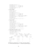
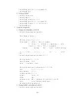
Display the routing table on Switch D.
[SwitchD] display bgp routing-table
Total Number of Routes: 2
BGP Local router ID is 194.1.1.1
Status codes: * - valid, > - best, d - damped,
h - history, i - internal, s - suppressed, S - Stale
Origin : i - IGP, e - EGP, ? - incomplete
Network NextHop MED LocPrf PrefVal
Path/Ogn
*>i 1.0.0.0 193.1.1.1 0 200 0 100i
* i 192.1.1.1 0 100 0 100i
You can find route 1.0.0.0/8 from Switch D to Switch C is the optimal.
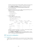
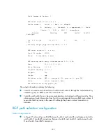
Configuring BFD for BGP
Network requirements
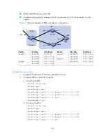
The following is shown in Figure 96:
•
Switch A and Switch B are interconnected through a Layer 2 switch. BFD is enabled on the
connected interfaces. BGP is enabled on the switches that are reachable to each other at the
network layer.
•
When the link between Switch A and Switch B fails, BFD can quickly detect the failure and
notify it to BGP.
Summary of Contents for S9500E Series
Page 435: ...435 ...