Operation Manual – VLAN-VPN
H3C S3100 Series Ethernet Switches
Chapter 4 BPDU Tunnel Configuration
4-2
address is used to identify the corresponding proprietary protocol, and the type field is
used to identify the specific protocol type.
II. Transmitting BPDU packets transparently
As shown in
Figure 3-1
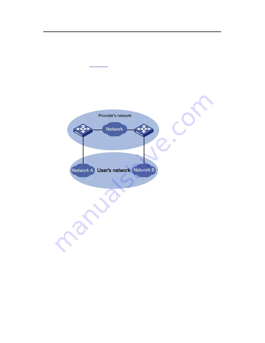
, the network on the top is the service provider network, and the
one on the bottom is a customer network. The service provider network contains edge
devices connecting the customer network to the service provider network. The
customer network contains Network A and Network B. You can make the BPDU
packets of the customer network to be transmitted in the service provider network
transparently by enabling the BPDU tunnel feature on the edge devices at both ends of
the service provider network.
Figure 4-1
BPDU Tunnel network hierarchy
z
When a BPDU packet coming from a customer network reaches an edge device in
the service provider network, the edge device changes the destination MAC
address carried in the packet from a protocol-specific MAC address to a private
multicast MAC address, which can be defined using a command. A packet with
this multicast address as its destination address is called a tunnel packet. In the
service provider network, the tunnel packet can be forwarded as a normal data
packet.
z
Before the device in the service provider network forwards the packet to the
destination customer network, the edge device will identify the tunnel packet,
determine the packet type based on the type field in the packet, restore its
destination MAC address to the original protocol-specific MAC address and then
forward the packet to the access device on the user side. This ensures the packet
to be forwarded is consistent with the packet before entering the tunnel. So, a
tunnel here acts as a local link for user devices. It enables Layer 2 protocols to run
on a virtual local network.


