background image

19

• 

Los distribuidores de vídeo son diferentes según se instale

cable coaxial o par trenzado. Los distribuidores de señal de vídeo

no van incluidos en los kit digitales.

IMPORTANTE: En instalaciones con accesos secundarios,

el cable de vídeo parte desde la placa calle principal y

recorre en serie las placas calle de los accesos secundarios,

y desde el último de estos accesos sube hacia las viviendas.

Los distribuidores se alimentan de forma diferente, según el tipo

de cable utilizado:

• Desde los monitores en instalaciones con cable coaxial:

mediante un cable desde la salida de alimentación para

distribuidores (borna 14) de cada uno de los monitores

conectados  a  las  salidas  derivadas  del  distribuidor.

• Desde los monitores en instalaciones con par trenzado:

además del cable indicado en el primer punto, también hay

que conectar al distribuidor el cable número 2M del bus

digital.

En ambos casos, el distribuidor sólo recibe alimentación cuando

uno de los monitores conectados a él está en funcionamiento.

Todos los distribuidores llevan incorporada una resistencia de

terminación de línea, que se ha de cortar si el distribuidor no es

el último de su rama de distribución; es decir, el cable de vídeo

entra al distribuidor y sale hacia otro distribuidor o monitor desde

su salida directa (no confundir la salida directa del distribuidor

con sus salidas derivadas).

• 

Video distributors will be different depending on whether coaxial

or twisted pair cable is installed. Video signal distributors are not

included in the digital kits.

IMPORTANT: in installations with secondary accesses, the

video cable starts from the main street panel and runs along

the street panel of the secondary in series, going up to the

dwellings from the last one of these accesses.

The distributors are powered differently according to the type of

cable used:

• 

From monitors in installations with coaxial cable: 

by

means of a cable from the power output for distributors

(terminal block 14) of each of the monitors connected to the

outputs  deriving from the distributor.

• 

From monitors in installations with twisted pair cable:

apart from the cable indicated in the point above, cable

number 2M of the digital bus will also be connected to the

distributor.

In either case, the distributor will only receive power supply when

one of the monitors connected to it is working.

All distributors include a line-end resistance, that will be cut off if

the distributor is not the last along its distribution branch; that is

to say, the video cable enters the distributor and exits towards

another distributor or monitor from its direct output (the direct

output of the distributor should not be mistaken for its deriving

outputs).

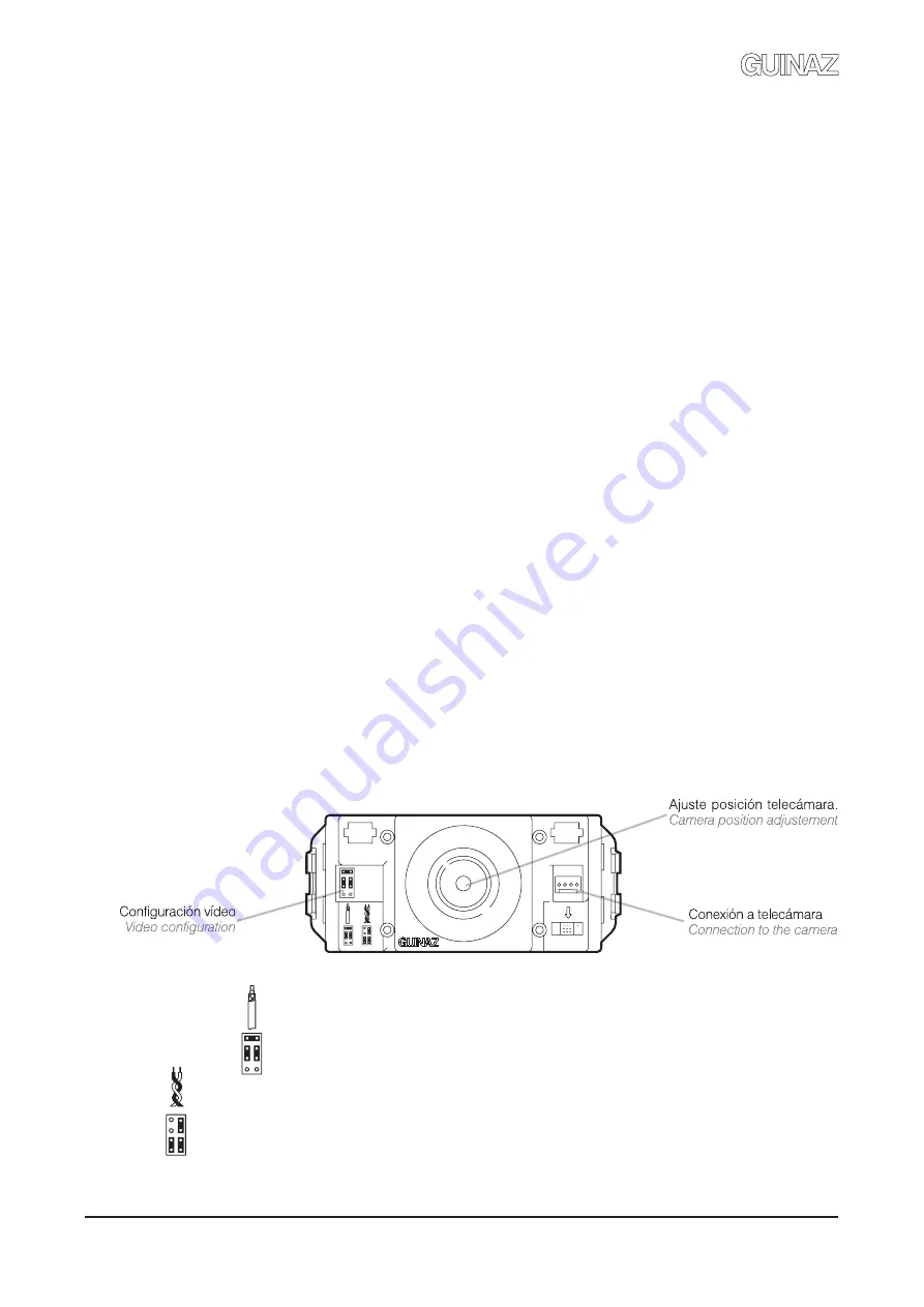
4.3 CONFIGURACIÓN DE LA TELECÁMARA (PLACA CALLE).


CONFIGURATION OF THE CAMERA (STREET PANEL).

Las telecámaras poseen tres puentes que se han de configurar

según se instale cable coaxial (75 ohmios) o par trenzado cat.5

(100 ohmios) para la transmisión de la señal de vídeo. Por defecto,

los puentes van colocados de fábrica en la posición para cable

coaxial (75 ohmios).

Cameras have three bridges to be configured according to whether

coaxial cable (75 ohms) or cat.5 twisted pair cable (100 ohms)

is installed for the transmission of the video signal. By default, the

bridges come in coaxial cable (75 ohms) position as standard.

Configuración puentes para instalaciones con cable de vídeo coaxial 75 ohmios.

Configuration of the jumpers for installations with 75 ohm coaxial cable.

Configuración puentes para instalaciones con cable par trenzado cat.5 (100 ohmios).

Configuration of the jumpers for installations with Cat. 5 (100 ohm) twisted pair cable.

G503130 - R01

Summary of Contents for M1717V2E

Page 1: ...GUÍA DE INSTALACIÓN INSTALLATION GUIDE KITS DIGITALES VIDEOPORTERO DIGITAL VIDEO ENTRYPHONE KITS ...

Page 2: ...710V2 M3740V2 15 3 7 Instalación caja empotrable y monitor M1717V2E M1747V2E Installation of flush mounted box and monitor M1717V2E M1747V2E 16 3 8 Recomendaciones de instalación de los monitores Recommendations for the installation of monitors 17 4 Configuración de los equipos Configuration of the equipment 18 4 1 Configuración del grupo control audio placa calle Configuration of the audio contro...

Page 3: ...ts de videoportero digitales se puede instalar un abrepuertas de corriente continua 12Vdc 400mA máximo o un abrepuertas de corriente alterna 12Vac 1A máximo Más adelante se indica cómo se conectan los dos tipos En el caso de los kits que incorporan abrepuertas de serie siempre son abrepuertas de corriente continua Estos equipos son para uso exclusivo en instalaciones de porteros GUINAZ Su instalac...

Page 4: ...ara abrir la puerta Door opener push button This is pressed to open the door 3 Pulsador comunicación Sirve para establecer comunicación audio entre placa calle y monitor siempre y cuando el monitor se haya encendido previamente Communication push button This is used to establish audio communication between the street panel and the monitor as long as the monitor has been previously turned on 4 Puls...

Page 5: ...the street panels El cableado del sistema digital de Guinaz consiste en un bus de 3 hilos para las señales de audio datos y alimentación con los que se interconectan todos los equipos de la instalación Estos tres hilos pueden ser de cualquier tipo de los que habitualmente se encuentran en el mercado pero con una única exigencia la sección de los cables debe ser la adecuada para la instalación a re...

Page 6: ...o teléfonos supletorios las distancias máximas para cada sección varían consulte los puntos 2 4 y 2 5 2 1 ESQUEMA UNIFILAR Y TABLA DE SECCIONES SINGLE WIRE DIAGRAM AND SECTION TABLE 2 ESQUEMAS DE CONEXIÓN CONNECTION DIAGRAMS Conexiones Connections 1M 2M 3M Secciones mm Sections mm Nº de hilos Nº of wires 3 25 m Distancias máximas metros Maximum distances meters 120 m 180 m 60 m 0 22 1 1 5 0 5 300 ...

Page 7: ...e street panel and the door opener is made using two cables NO and terminal blocks of the audio control group Terminal blocks 12 and C will connect to each other by means of a cable An auxiliary external pushbutton may be connected between terminal blocks C and NO in order to activate the door opener The time the door opener is activated when the auxiliary external pushbutton is pressed does not h...

Page 8: ...gital video entryphone kits The power supply of the system is carried out by means of the cables joining terminal blocks 1 and 2 of the power supply with terminal blocks 1M and 2M of the audio control group of the street panel Each distributor is powered by terminal block 14 of the monitors connected to its deriving outputs Terminal blocks 14 of distributors must not be joined to each other MONITO...

Page 9: ...nal pushbutton is pressed does not have a timer that is to say it will only remain active while this external pushbutton is being pressed G503130 R01 2 4 ESQUEMA DE CONEXIONES CON CABLE UTP CAT 5 SCHEMATIC INSTALLATION WITH UTP CAT 5 CABLE MONITOR n 4 V H M L M L 1M 2M 3M 12 13 14 Abrepuertas 12 Vdc 400mA máx Door opener 12 Vdc max 400mA Pulsador auxiliar abrepuertas Auxiliary door opener push but...

Page 10: ...ording to the amount of supplementary telephones installed The following tables indicate the maximum distances according to the cable cross section for installations with a monitor and 1 2 or 3 supplementary telephones per dwelling TABLA SECCIONES MONITORES BLANCO Y NEGRO CON TELÉFONOS SUPLETORIOS SECTIONS TABLE FOR B W MONITORS WITH SUPPLEMENTARY TELEPHONES 120 m 1 5 90 m 60 m 1 Monitor 2 Teléfon...

Page 11: ...ún la cantidad de monitores supletorios instalados los valores de las tablas de secciones del punto 2 1 varían Las tablas siguientes indican las distancias máximas según la sección de cable para instalaciones con un monitor principal más 1 ó 2 monitores supletorios por vivienda The micro switches of the supplementary monitor are configured as follows The first 8 micro switches are placed in the sa...

Page 12: ...roup of the street panel power supply F1318 and the alternating current door opener 2 7 CONEXIÓN DE ABREPUERTAS DE CORRIENTE ALTERNA CONNECTION OF ALTERNATING CURRENT DOOR OPENERS The time the door opener is activated when the auxiliary external pushbutton is pressed does not have a timer that is to say it will only remain active while this external pushbutton is being pressed 12 220 Vac F1318 PRI...

Page 13: ...AY QUE QUITAR LAS TAPAS SUPERIOR E INFERIOR Sólo es necesario soltar un tornillo y aflojar el otro consulte los apartados 3 y 4 LAS TAPAS SUPERIOR E INFERIOR SÓLO PUEDEN PONERSE O QUITARSE CON LA PLACA CALLE ABIERTA Una vez cerrada ésta las patillas de anclaje de las tapas quedan atrapadas por la propia placa para evitar acciones vandálicas 3 2 COLOCACIÓN DE LOS TARJETEROS PLACEMENT OF NAME TAGS E...

Page 14: ...o de la alimentación Internal handling of the equipment may only be performed by specialised personnel always once the equipment has been disconnected from the power supply En la instalación de videoportero se ha de escoger un lugar donde no incida directamente una fuente de luz sol farolas etc sobre la telecámara para evitar el efecto de contraluz en la imagen En el caso de que la imagen no sea n...

Page 15: ...y 4 5 y conecte el latiguillo del monitor Configure the connection card of the wall base as indicated in points 4 4 and 4 5 and connect the connector of the monitor 2 3 4 5 Colocación del monitor A Encaje el monitor sobre la base mural B Presione hacia abajo hasta oír el clip Placing the monitor A Fit in the monitor onto the wall base B Press downwards until it clips in Conecte el auricular al mon...

Page 16: ...as deslizantes de tal forma que las superficies de referencia indicadas queden a ras de la pared Cuando estas superficies queden niveladas sujetar las patillas con los tornillos de apriete Before installing the monitor adjust the sliding strips in such a way that the reference surfaces are at wall level Once levelled tighten the strips with the screws for tightening 3 5 4 Colocación monitor A Enca...

Page 17: ...ar obstruidas o tapadas Los monitores están diseñados para ser instalados en interiores no se han de exponer a gotas o proyecciones de agua Se recomienda instalar los monitores en lugares desde los cuales se escuche la llamada en toda la vivienda y que estén alejados de fuentes de calor radiadores estufas etc o de ambientes agresivos cocinas etc 3 8 RECOMENDACIONES DE INSTALACIÓN DE LOS MONITORES ...

Page 18: ...guración por defecto de las telecámaras también es para cable coaxial 75 ohmios En el punto 4 3 se indica cómo configurar los puentes de las telecámaras según el tipo de cable instalado The video signal can be distributed both via a 75 ohm coaxial cable and with a category 5 twisted pair cable 100 ohms Although the installations for both cables are similar there are some differences to be taken in...

Page 19: ...s from the last one of these accesses The distributors are powered differently according to the type of cable used From monitors in installations with coaxial cable by means of a cable from the power output for distributors terminal block 14 of each of the monitors connected to the outputs deriving from the distributor From monitors in installations with twisted pair cable apart from the cable ind...

Page 20: ...ne the video cable only enters the card there is no need to change the 75 ohm resistance that comes in position R1 of the connection card as standard In video installations using cat 5 Twisted pair cable 100 ohms and with the monitor being the last along its distribution line the video cable only enters the card the 75 ohm resistance in position R1 has to be cut off and the 100 ohm resistance prov...

Page 21: ...ón el cable de vídeo entra y sale de la tarjeta de conexiones tanto en instalaciones de coaxial como de par trenzado sólo hay que cortar la resistencia de 75 ohmios colocada en la posición R1 SIN RESISTENCIA de terminación If the monitor is not the last one along its distribution branch the video cable enters and exits the connection card it will only be necessary to cut the 75 ohm resistance in p...

Page 22: ...t panel has audio volume adjustment for the street panel and the dwellings monitors by means of the potentiometers the audio control group includes The position of the street panel camera can also be adjusted to focus on the area that is to be viewed on the monitors Cuando desde un pulsador de la placa calle se efectúa una llamada el monitor de la vivienda se enciende automáticamente y muestra la ...

Page 23: ...a de 100 ohmios Este contacto admite tensiones con un máximo de 17V y corrientes con un máximo de 40mA El botón auxiliar AUX puede utilizarse para activar funciones ajenas a la instalación de videoportero Terminals 12 and 13 of the monitor connection card are potential free contacts AUX button via a limiting resistance of 100 ohms This contact admits maximum voltages of 17V and maximum currents of...

Page 24: ...at 5 twisted pair cable If this is not the case check the configuration of the bridges in monitors and cameras and the line end resistance in the distributors Check there is no short circuit between lines 1M 2M and 3M Hands free kits also have the call tone volume regulation function in the monitor The following process will be followed With the monitor in idle state press and keep pressing on the...

Page 25: ...sejamos desconectar la instalación por tramos hasta localizar el problema Si con los cables 1M 2M y 3M desconectados las tensiones no son correctas desconecte los cables 1 y 2 en la fuente de alimentación y compruebe las tensiones en bornas de entrada 220Vac y de salida 17Vdc Si no hay 17Vdc en la salida la fuente de alimentación puede estar averiada Si la fuente de alimentación funciona correctam...

Page 26: ...mara puede estar averiada Check that the connection strap between the audio control unit and the camera is correctly connected Verify correct configuration of the street panel micro switches of the audio control unit Check that the installed cable complies with the following technical specifications 75 ohm impedance coaxial cable or cat 5 100 ohm impedance twisted pair cable Revise the connection ...

Page 27: ...as NO y GND cuando se intenta abrir la puerta desde una vivienda Si estas tensiones no son correctas el grupo control audio puede estar averiado Si se ha instalado un abrepuertas de corriente alterna compruebe las conexiones entre el grupo de audio la fuente F1318 y el abrepuertas según el esquema del punto 4 6 de esta guía Compruebe que el abrepuertas de alterna cumple con las siguientes especifi...

Page 28: ... G503130 G503130 R01 ...

Reviews: