background image

Installation and Use


G

ua

rd

ia

Fa

ll 

Pr

ot

ec

tio

  6

30

S.

 2

31

st

 S

t.

, K

en

t,

 W

A

 9

80

32


 p

ho

ne

: (

80

0)

 4

66

-6

38

 f

ax

: (

80

0)

 6

70

-7

89


  w

w

w

.g

ua

rd

ia

nf

al

l.c

om

11

The Rack is a welded steel frame for placement on a building’s parapet, and functions to assist in
window washing applications. Parapet must withstand loads of at least 5,000 lbs., as
determined by a Qualified Person.

Prior to Installation:

1. Optional foot extender is for use on parapets with an overhang of 12” or less.

2. Make considerations for eliminating or minimizing swing fall hazards.

3. Extreme care must be taken when using descent equipment near electrical sources, heat,
and turbulent or unstable areas, such as air vents.

4. All PFAS equipment must be deemed compatible by a Competent Person. Always read and
understand all PFAS equipment instructions.

5. Compatible with parapets between 10“ - 24” wide. NEVER attempt to attach to parapets wider
than 24”. Parapet must be at least 10“ in height. After installation, The Rack must be fully flush
and fully set on parapet.

6. Window washing ropes must not be used longer than 2 years from Date of First Use, or
3 years from Date of Manufacture. On descents exceeding 130’, provisions must be made for
continuous suspension, intermittent suspension, or for a work station. Descents must never
exceed 300’.

Installation:

1. Remove (4) Connector Pins and set Frame Assembly aside.

2. Extend Foot Assembly to desired length. Suggested distance is 4’ below top of parapet.

3. If parapet has overhang, remove Foot Assembly from Frame Assembly and slide optional Foot
Extender onto Foot Assembly, adjusting its length to accommodate the overhang. Then, re-insert
Foot Assembly into Frame Assembly.

4. Install (2) Connector Pins to connect Foot Assembly to Frame Assembly.

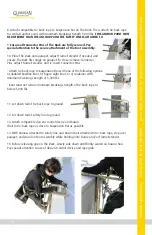
5. Slide Frame Extender into Frame Assembly to location where The Rack will fit snugly onto the
parapet, then connect them with (2) remaining Connector Pins.

6. Attach safety line to certified anchor point with minimum breaking
strength 5,000 lbs. 

THIS ANCHOR POINT MUST BE SEPARATE FROM THE

ANCHOR POINT THE TIE-BACK ROPE WILL BE ATTACHED TO.

 Safety line

must be directly in line with anchor point.

7. If parapet is 42” or lower, attach to safety line before coming within 6’
of fall hazard. ALWAYS use complete and compatible PFAS.

Summary of Contents for 15169

Page 1: ...Product Name The Rack Instruction Manual Part 15169 Do not throw away these instructions Read and understand these instructions before using equipment...

Page 2: ......

Page 3: ...otection The Rack This manual must be read and understood in its entirety and used as part of an employee training program as required by OSHA or any applicable state agency This and any other include...

Page 4: ...SIGNED BY THE EMPLOYER to be responsible for all elements of a fall safety program including but not limited to its regulation management and application A person who is proficient in identifying exis...

Page 5: ...s must not exceed 6 No free fall allowed for non LE SRLs SRLs must arrest falls within 54 Forces applied to anchors must be calculated by a Competent Person Harnesses and connectors selected must be c...

Page 6: ...n excessive wear fraying knotting abrasion and absence of parts Equipment that fails inspection in any way must immediately be removed from use or repaired by an entity approved by the manufacturer No...

Page 7: ...ot limited to corrosion deformation pits burrs rough surfaces sharp edges cracking rust paint buildup excessive heating alteration and missing or illegible labels IMMEDIATELY remove The Rack from serv...

Page 8: ...shing applications and prevent fraying or breaking of suspension and tie back ropes The Rack is not a component of a PFAS and MUST ALWAYS be used in combination with a complete and compatible PFAS NEV...

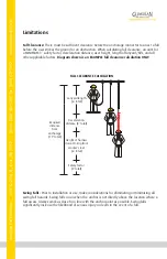
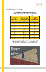
Page 9: ...r deceleration distance user height length of lanyard SRL and all other applicable factors Diagram shown is an EXAMPLE fall clearance calculation ONLY Swing Falls Prior to installation or use make con...

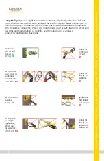
Page 10: ...inimum loads of 3 600 lbs See the following for examples of compatible incompatible connections Connector closed and locked to D ring OK Two or more snap hooks or carabiners connected to each other NO...

Page 11: ...6 10 15 20 25 30 35 40 45 50 55 60 8 9 9 11 7 13 3 14 6 16 17 2 18 3 19 4 19 10 21 4 22 3 53 45 38 33 30 28 26 24 23 21 21 21 For example if the anchorage connector is 6 from the leading edge Y the wo...

Page 12: ...Fall Protection 6305 S 231st St Kent WA 98032 phone 800 466 6385 fax 800 670 7892 www guardianfall com 10 Frame Assembly Foot Assembly Frame Extender 4 Connector Pins Materials galvanized steel Weigh...

Page 13: ...pes must not be used longer than 2 years from Date of First Use or 3 years from Date of Manufacture On descents exceeding 130 provisions must be made for continuous suspension intermittent suspension...

Page 14: ...ame Extender and re insert Connector Pins Attach tie back rope to Suspension Bar with one of the following options a doubled bowline knot b figure eight knot or c carabiner with minimum breaking stren...

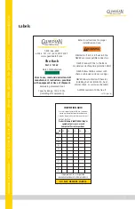
Page 15: ...T REMOVE LABELS YR MO The Rack Part 15169 Prior to use read and understand all manufacturer s instructions provided with equipment at time of shipment WARNING Eliminate all risk of roll out in PFAS NE...

Page 16: ...ate of First Use __________________ Product lifetime is indefinite as long as it passes pre use and Competent Person inspections This inspection log must be specific to one The Rack Separate inspectio...

Reviews: