- 9 -
HDM 2380 P CI / HDM 2380 OIRT CI
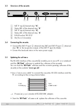
3.3 Overview of the cassette
5
6
3
2
4
1
1
SAT IF input (channel strip “
B
”)
2
Status LED of the channel strip “
B
”
3
SAT IF input (channel strip “
A
”)
4
Status LED of the channel strip “
A
”
5
D-SUB socket “RS 232“
6
Slot for a CA module
3.4 Connecting the cassette
• Connect the SAT IF input
3
(channel strip “
A
”) and SAT IF input
1
(channel
strip “
B
”) to the respective outputs of the SAT IF input distributor.
•
Connect the head-end station to the mains power supply.
3.5 Updating the software
The RS 232 interface of the cassette
$
enables you to use a PC or a notebook
and the “
BE-Flash
” software to update the software of the cassette.
You can find the “
BE-Flash
” software and the current operating software of the
cassette at the website “
www.gss.de
”.
• Use a “one-to-one cable” to connect the cassette’s RS 232 interface and the
PC according to the wiring scheme below.
9-pin
D-SUB socket
9-pin
D-SUB plug
1
2
3
4
5
6
7
8
9
1
2
3
4
5
6
7
8
9
—> If necessary use a standard RS-232/USB adapter.
• Start the “
BE-Flash
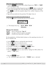
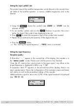
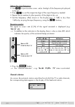
” software and update the software of the cassette.


