- 6 -
HDM 2380 P CI / HDM 2380 OIRT CI
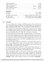
Output impedance: ......................................................................... 75
Ω
Video interference level: .................................................................57 dB
Video band width: ......................................................... 20 Hz … 5 MHz
Audio interference level: .................................................................60 dB
Audio band width: ......................................................... 40 Hz … 15 kHz
Connections
SAT inputs: ............................................................................. 2 F sockets
HF output: ............................................................................ 1 IEC socket
Connection strip (10-pin): ...................
for supply voltages and control circuits
RS 232 socket: ..................................... serial interface for software update
Conditional access: ...............................1 (2 channels can be descrambled)
2.4 Description
The twin transmodulator cassette is a QPSK-converter, which converts all sta-
tions modulated according to DVB-S and QPSK standard into two PAL-modu-
lated cable signals (HDM 2380 P CI in CCIR standard/ HDM 2380 OIRT CI in
OIRT standard). The cassette has two digital SAT IF inputs and one HF output.
It is equipped with two channel strips. Each channel strip consists of a digital
tuner, a digital signal preparation unit and a modulator. The cassette‘s channel
strips are indicated by “
Bx …A
“ or “
Bx …B
” in the control unit display.
The channel strip “
A
” can descramble scrambled channels via a correspond-
ing CA module. Depending on the CA module and the smart card, two chan-
nels can be descrambled simultaneously with one CA module, with the second
one supplied via channel strip “
B
”. Using the integrated time control you can
select alternate channels. The control of the cassette takes place via the control
unit of the head-end station.
Two LEDs provide an indication of the SAT IF input signal quality based on
their colour. Additionally the quality of the transport stream received is dis-
played (“
CN…
”). If the data of channel strip ”
A
” are used in channel strip ”
B
”
the status LED of channel strip ”
B
” is switched off.
The prepared input signals reach
t
he HF output collector of the head-end sta-
tion via the HF output socket. The common output level of the channel strips
can be set at the HF output collector of the head-end station.
When the head-end station is switched on, the two-line LC display briefly
shows the software version of the control unit. To operate this cassette the
software version of the control unit must be “
V 41
” or higher. You can find the
current operating software for the control unit and the cassette, the software
“
BE-Flash
” and the current assembly instructions on the website “
www.gss.de
”.


