background image


- 28 - 

HDM 2380 P CI / HDM 2380 OIRT CI


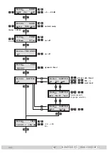
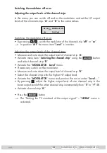
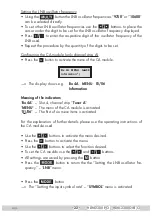
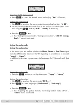
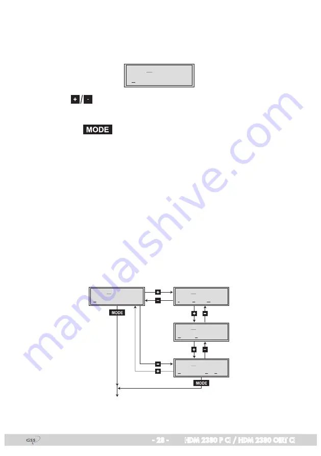
Locking the regional window


In this menu the dynamic switch over between the main channel and the as-
sociated regional channels can be deactivated.

Bx 4A

/B

 dynamic

PIDS


•  Press 

 to switch on the dynamic regional switch over (“

dynamic

”) or 

off (“

fixed

”).


•  Press the 

 button.


—>  The “Subtitle settings” – “

SUBTITLE

” menu is activated.


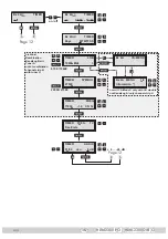
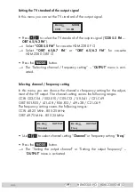
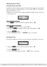
Subtitle settings


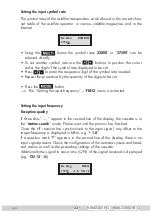
In this menu you define wether subtitles are to be transmitted or not. If the trans-
mission of subtitles is switched on (“

txt

”) subtitles transmitted in the teletext are 

displayed directly in the station. For this you can activate the page wished.


In addition in this menu you define the characters to display the languages. For 
the Western European languages set “

West

”; for Eastern European languages 

set “

East

”.


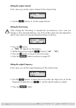
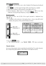
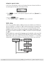
If DVB subtitles are received, the language can be selected in this menu. But 
the respective menu only is displayed if the DVB data stream contains subtitles.


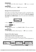
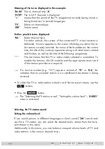
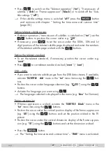
Additionally in this menu a part of the TV picture is blanked, i. e. covered by 
a black strip. The vertical dimension and the position of the strip can be set.

Bx 4A

/B

txt 

150  west 

SUBTITLE

Bx 4A

/B

off

SUBTITLE

Bx 4A

/B

dvb  01 / 02

SUBTITLE

"deu"

Bx 4A

/B

black 

40 / 10

SUBTITLE

Summary of Contents for HDM 2380 OIRT CI

Page 1: ...SS Grundig SAT Systems GmbH Beuthener Strasse 43 D 90471 Nuremberg Phone 49 0 911 703 8877 Fax 49 0 911 703 9210 E mail info gss de Internet http www gss de HDM 2380 P CI HDM 2380 OIRT CI Head End Digital Modulator QPSK PAL ...

Page 2: ...g procedure 12 5 3 Programming the cassette 16 Selecting the cassette displaying the software version 16 Selecting the channel strip 17 Switching the modulator off or on 18 Adjusting the output levels of the channel strips 18 Setting the TV standard of the output signal 19 Selecting channel frequency setting 19 Setting the output channel 20 Setting the fine tuning 20 Setting the output frequency 2...

Page 3: ...olled alternative channels 31 Switching the timer on and off 31 Setting the duty cycle 31 Setting the days of the week 31 Setting the LNB oscillator frequency timer 32 Configuring the CA module timer only channel strip A 32 Setting the input symbol rate timer 32 Setting the input frequency timer 33 Channel selection timer 33 Selecting the TV station sound Setting the volume level timer 33 Saving s...

Page 4: ...ort circuits No liability is accepted for any damage caused by faulty connections or inappropriate handling Observe the relevant standards regulations and guidelines on the installa tion and operation of antenna systems The standards IEC EN DINEN50083 and IEC EN DINEN60728 must be observed For further information please read the assembly instructions for the head end station used Test the software...

Page 5: ... 2004 108 EC The product fulfils the guidelines and standards for CE labelling Unless otherwise noted all values are specified as typical HF input Frequency range 950 2150 MHz Level range 60 dBμV 80 dBμV Input impedance 75 Ω Symbol rate 1 45 Msymb s HF output Channels HDM 2380 P CI C2 C69 incl S2 S41 HDM 2380 OIRT CI R1 C69 incl s1 s38 Frequency range HDM 2380 P CI 48 25 MHz 855 25 MHz HDM 2380 OI...

Page 6: ...respond ing CA module Depending on the CA module and the smart card two chan nels can be descrambled simultaneously with one CA module with the second one supplied via channel strip B Using the integrated time control you can select alternate channels The control of the cassette takes place via the control unit of the head end station Two LEDs provide an indication of the SAT IF input signal quali...

Page 7: ...ion of the cassette is displayed see page 16 3 Assembly 3 1 Installing the cassette Ensure the head end station is mounted so it will not be able to vibrate Avoid for example mounting the head end station onto a lift shaft or any other wall or floor construction that vibrates in a similar way Before installing or changing a cassette unplug the power cable from the mains power socket Remove the fas...

Page 8: ...nd station using cable terminals CLASS KLASSE The attenuation of shielding of the connection lines must meet the requirements for Class A When mounting the cassette in a head end station which is installed in a 19 cabinet make sure the connections leading in and out for the 19 cabinet are made using cable terminals Insert the required number of cable terminals in the openings provided in the head ...

Page 9: ... the head end station to the mains power supply 3 5 Updating the software The RS 232 interface of the cassette enables you to use a PC or a notebook and the BE Flash software to update the software of the cassette You can find the BE Flash software and the current operating software of the cassette at the website www gss de Use a one to one cable to connect the cassette s RS 232 interface and the ...

Page 10: ...le for descrambling several channels The hardware and software of this cassette have been thoroughly prepared and tested Any changes made by program providers to the structures in the program data might impair or even prevent this function When working with the CA module please read the corresponding operat ing manual from the respective provider Insert the smart card 1 into the CA module 2 so tha...

Page 11: ...election Output channel output frequency CA module if available LNB oscillator frequency Input symbol rate Input frequency Channel selection TV station sound Volume Audio mode Audio output Picture format Teletext Test lines Regional window Subtitle Time zone and summer time Timer settings Factory reset 4 2 Control panel The key pad on the head end station is used to scroll through the menus and me...

Page 12: ... and adjust the TV test receiver to this channel this frequency Switch on the modulator if necessary page 18 Balance the output levels of the channel strips A and B if the difference in level is 1 dB see chapter Modulator settings Adjusting the output levels of the channel strips page 18 5 2 Programming procedure Ein On BE Remote please wait V 41 Box 4 V 3 QPSK PAL Bx 1A C5 12 S3 24 TWIN SAT C07 B...

Page 13: ...4A B Channel OUTPUT Channel Freq 9750 10600 Bx 4A B 27500 SYMBOL 22000 27500 Bx 4A B 11953 1 8 FREQ CN 12 6 26 dB Bx 4B Tuner Line B INPUT Tuner A Tuner B nur Kanalzug B only channel strip B nur mit CA Modul only with CA module Bx 4A Tuner B Bx 4B Die angezeigte Information ist abhängig vom verwendeten CA Modul The information displayed is dependent on the CA module used Bx 4A MENU Information 1 6...

Page 14: ...ormal swap mpeg stereo Bx 4A B WSS on VIDEO TXT on on off Bx 4A B on TESTLINES on off Bx 4A B dynamic PIDS dynamic fixed on off Bx 4A B off SUBTITLE 100 n west east off txt dvb black Bx 4A B dvb 01 02 SUBTITLE deu 6 26 dB Bx 4A B 14 20 11 TIME 01 S 12 12 S Bx 4A B off TIMER Bx 4A B on TIMER 05 00 10 00 Bx 4A B TIMER on off M B A Bx 4A B black 40 10 SUBTITLE ...

Page 15: ... Bx 4A B off TIMER Bx 4A B on TIMER 05 00 10 00 Bx 4A B Days TIMER MTWTFSS on off 6 26 dB TIMER 27500 SYMBOL 22000 27500 M M B A nicht bei Kombination Kanalzug B mit Tuner A not at combination channel strip B with tuner A nur mit CA Modul only with CA module nur Kanalzug A only channel strip A Bx 4A MENU Information 1 6 Bx 4A CA MENU Page 12 Page 12 ...

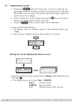
Page 16: ...ing the button previous menus can be activated Switch on the head end station The display shows the software version of the head end station e g V 41 The processor reads the cassettes data approx 10 seconds Ein On BE Remote please wait V 41 t 10 s Selecting the cassette displaying the software version Box 4 V 3 QPSK PAL Bx 1A C5 12 S3 24 TWIN SAT C07 Böx 4 C5 12 S3 24 TWIN SAT C07 Box 5 Box Select...

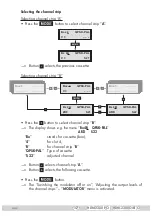
Page 17: ...A ZDF QPSK PAL S21 Bx 4B ARD QPSK PAL S22 Box 5 Box 3 Press the button to select channel strip B The display shows e g the menu Bx 4B QPSK PAL ARD S22 Bx stands for cassette box 4 for slot 4 B for channel strip B QPSK PAL Type of cassette S 22 adjusted channel Button selects channel strip A Button selects the following cassette Press the button The Switching the modulator off or on Adjusting the o...

Page 18: ...l strips Measure and note down the output level of channel strip A Activate menu item Selecting the channel strip using the button and select channel strip B Activate the MODULATOR Level menu If necessary switch on the modulator Measure and note down the output level of channel strip B Select the channel strip with the higher HF output level Activate the MODULATOR menu and position the cursor unde...

Page 19: ...tting OUTPUT menu is acti vated Selecting channel frequency setting In this menu you can choose the channel or frequen cy setting for the adjust ment of the HF output The channel setting covers the following ranges CCIR C02 C04 S02 S10 C05 C12 S11 S41 C21 C69 OIRT R01 R05 s01 s08 R06 R12 s09 s38 C21 C69 The frequency setting covers the following ranges CCIR 48 25 MHz 855 25 MHz OIRT 49 75 MHz 855 ...

Page 20: ... must be adjusted to match it by means of corresponding fine tuning corrections Bx 4A B S21 Fine OUTPUT 0 Press the button FINE 0 appears in the display Set the fine tuning using the buttons 64 63 Press the button to return to the main menu Press the button continue on page 21 Setting the output frequency In this menu you set the output frequency of the channel strip Bx 4A B 303 25 OUTPUT Use the ...

Page 21: ...scramble two scrambled channels using a CA module and a corresponding smart card Bx 4B Tuner Line B INPUT Press the buttons to select the tuner wished Press the button Selection Tuner A The Channel selection e g Bx 4B 01 09 TV menu is activated page 24 Selection Tuner B The Setting the LNB oscillator frequency LNB menu is activated Setting the LNB oscillator frequency Configuring the CA module onl...

Page 22: ...menu of the CA module Bx 4A MENU Information 01 06 The display shows e g Bx 4A MENU 01 06 Information Meaning of the indicators Bx 4A Slot 4 channel strip Tuner A MENU The menu of the CA module is activated 01 06 The first of six menu items is activated For the explanation of further details please use the operating instructions of the CA module used Use the buttons to activate the menu desired Pr...

Page 23: ...antity of the digits to be set Press the button The Setting the input frequency FREQ menu is activated Setting the input frequency Reception quality If three dots appear in the second line of the display the cassette is in the station search mode Please wait until the process has finished Once the HF receiver has synchronised to the input signal any offset to the target frequency is displayed in M...

Page 24: ...ayed e g CN 12 dB In addition to the indicator in the display there is also a status LED which indicates the quality of the received transport stream LED indicator Indication Green Signal quality is good Yellow Signal quality is poor Red No signal The LED of chan nel strip B is switched off In the channel strip B the data of channel strip A are used Press the button The Channel selection e g Bx 4A...

Page 25: ...the following programme The star means that the TV or radio station selected is scrambled To enable the stations the CA module and the appropriate smart card of the station provider are required If a service number e g 131 appears instead of TV or RA this indicates that an unnamed station or an undefined data stream is being received To select the TV or radio station wished out of the transport st...

Page 26: ...mpeg Dual menu is activated Setting the audio mode Setting the audio output In this menu you can define whether the Mono Stereo or Dual Tone signal from the MPEG data stream or the VPS Signaling if available is to be used mpeg stereo In addition in this menu you can swap the languages for TV channels with dual tone Bx 4A B mpeg AUDIO DUAL norm Setting the audio mode Press the buttons to set the da...

Page 27: ...mitted or not Bx 4A B WSS on VIDEO TXT on Adjusting the picture format Press to switch Wide Screen Signaling on or off Switching teletext mode off on Use to position the cursor under TXT By pressing the teletext mode can be switched on or off Press the button The Activating test lines TESTLINES menu is activated Activating test lines For specific applications test lines can be inserted in the tele...

Page 28: ...es transmitted in the teletext are displayed directly in the station For this you can activate the page wished In addition in this menu you define the characters to display the languages For the Western European languages set West for Eastern European languages set East If DVB subtitles are received the language can be selected in this menu But the respective menu only is displayed if the DVB data...

Page 29: ...ard if necessary position the cursor under e g west Press to set teletext standard wished west east DVB subtitle If you want to activate subtitle pages from the DVB data stream if available activate SUBTITLE dvb menu in the txt menu item using the but tons Position the cursor under language selection e g 01 02 using the buttons Activate the language you want using The language selected is displaye...

Page 30: ...ansponder used Bx 4A B 14 20 11 TIME 01 S 14 20 11 Time GMT offset The current time is displayed when the question mark disappears 01 1 hour offset to GMT is set S Summer time support is switched on Example Summertime support for the time zone of Germany GMT 1 hour is in If S is switched on one hour is added in addition to offset 01 during summer time Using the buttons set the time zone you live i...

Page 31: ...34 Setting the duty cycle In this menu you set the duty cycle of the alternative channel Bx 4A B on TIMER 05 00 10 00 Use the buttons to position the cursor under the digits of the switch on time to be set e g 05 00 Press to set the desired switch on time Use the buttons to position the cursor under the digits of the switch off time to be set e g 10 00 Press to set the desired switch off time Pres...

Page 32: ...hich the timer should and should not be active Press the button The Setting the LNB oscillator frequency timer TIMER LNB menu is activated Setting the LNB oscillator frequency timer Configuring the CA module timer only channel strip A TIMER 10600 MHz LNB For setting see page 21 Press the button The Setting the input symbol rate timer TIMER SYMBOL menu is activated Setting the input symbol rate tim...

Page 33: ... see page 23 Press the button The Channel selection timer e g Bx 4A 01 07 TV menu is activated Channel selection timer TIMER 01 07 Das Erste TV For setting see page 24 Press the button The Selecting the TV station sound Setting the volume level timer TIMER AUDIO menu is activated Selecting the TV station sound Setting the volume level timer TIMER 01 02 deu AUDIO 6 dB For setting see page 25 ...

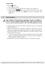
Page 34: ...s in order to maintain compliance with current EMC regulations securely Securely tighten the cable connections fingertight using an appropriate open ended spanner Measure the output levels of the other cassettes and tune them to a uniform output level using the appropriate level controls or software dependent on the head end station used Please regard the assembly instructions of the respective he...

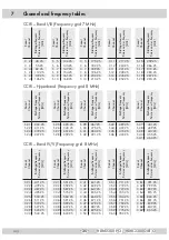
Page 35: ... 25 Kanal Channel Bildträgerfrequenz Picture carrier frequency MHz S 29 367 25 S 30 375 25 S 31 383 25 S 32 391 25 Kanal Channel Bildträgerfrequenz Picture carrier frequency MHz S 33 399 25 S 34 407 25 S 35 415 25 S 36 423 25 Kanal Channel Bildträgerfrequenz Picture carrier frequency MHz S 37 431 25 S 38 439 25 S 39 447 25 S 40 455 25 S 41 463 25 Kanal Channel Bildträgerfrequenz Picture carrier fr...

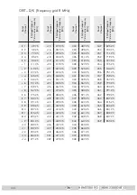
Page 36: ...7 25 s27 375 25 s28 383 25 s29 391 25 s30 399 25 s31 407 25 s32 415 25 s33 423 25 s34 431 25 s35 439 25 s36 447 25 s37 455 25 s38 463 25 C21 471 25 C22 479 25 Kanal Channel Bildträgerfrequenz Picture carrier frequency MHz C23 487 25 C24 495 25 C25 503 25 C26 511 25 C27 519 25 C28 527 25 C29 535 25 C30 543 25 C31 551 25 C32 559 25 C33 567 25 C34 575 25 C35 583 25 C36 591 25 C37 599 25 C38 607 25 C3...

Page 37: ...Alterations reserved Technical data E O E by GSS GmbH V3 22022010 Service Phone 49 0 911 703 2221 Fax 49 0 911 703 2326 Email service gss de ...

Reviews: