English (GB)
14
7.5 Signal cables
• Use screened cables with a cross-sectional area of minimum
0.5 mm
2
and maximum 1.5 mm
2
for external on/off switch,
digital inputs, setpoint and sensor signals.
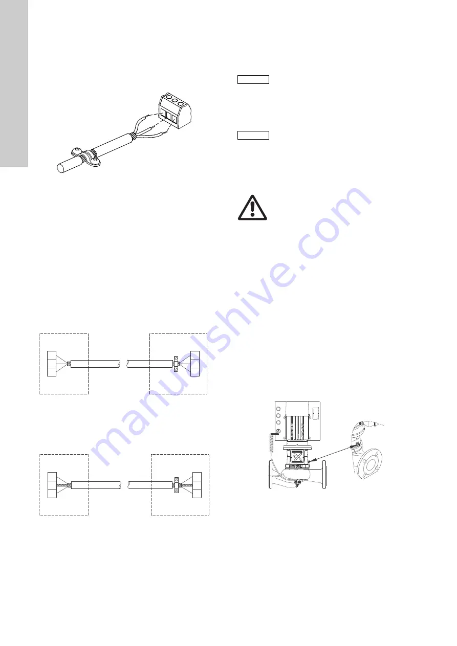
• Connect the screens of the cables to frame at both ends with
good connection. The screens must be as close as possible to
the terminals. See fig.
Fig. 21
Stripped cable with screen and wire connections
• Always tighten screws for frame connections whether a cable
is fitted or not.
• The wires in the motor terminal box must be as short as
possible.
7.6 Bus connection cable
7.6.1 New installations
For the bus connection, use a screened 3-core cable with a
cross-sectional area of minimum 0.5 mm
2
and maximum 1.5
mm
2
.
• If the motor is connected to a unit with a cable clamp which is
identical to the one on the motor, connect the screen to this
cable clamp.
• If the unit has no cable clamp as shown in fig.
, leave the
screen unconnected at this end.
Fig. 22
Connection with screened 3-core cable
7.6.2 Replacing an existing motor
• If a screened 2-core cable is used in the existing installation,
connect the cable as shown in fig.
Fig. 23
Connection with screened 2-core cable
• If a screened 3-core cable is used in the existing installation,
follow the instructions in section
8. Startup
8.1 Flushing the pipe system
8.2 Priming the pump
Closed systems or open systems where the liquid level is
above the pump inlet
1. Close the outlet isolating valve and loosen the vent screw in
the motor stool. See fig.
2. Slowly open the isolating valve in the inlet pipe until a steady
stream of liquid runs out of the vent hole.
3. Tighten the vent screw and completely open the isolating
valve(s).
Open systems where the liquid level is below the pump inlet
The inlet pipe and the pump must be filled with liquid and vented
before the pump is started.
1. Close the outlet isolating valve and open the isolating valve in
the inlet pipe.
2. Loosen the vent screw. See fig.
.
3. Remove the plug from one of the pump flanges, depending on
the pump location.
4. Pour liquid through the priming port until the inlet pipe and the
pump are filled with liquid.
5. Replace the plug and tighten securely.
6. Tighten the vent screw.
You can fill the inlet pipe with liquid and vent it before you connect
it to the pump. You can also install a priming device before the
pump.
Fig. 24
Position of vent screw
T
M
02
13
25
44
0
2
TM
05
3
973
18
12
TM
02
8
842
09
04
A
Y
B
A
Y
B
1
2
3
1
2
3
Motor
A
Y
B
A
Y
B
1
2
1
2
Motor
Caution
The pump is not designed to pump liquids containing
solid particles such as pipe debris and welding slag.
Before starting up the pump, clean the pipe system
thoroughly, and flush and fill it with clean water.
The warranty does not cover any damage caused by
flushing the pipe system by means of the pump.
Caution
Do not start the pump until it has been filled with
liquid and vented. To ensure correct venting, the vent
screw should point upwards.
Warning
Pay attention to the direction of the vent hole, and
make sure that the escaping hot or cold liquid does
not cause injury to persons or damage to the
equipment.
T
M
05
7
9
2
2
16
13


