En
gl
is
h (
G
B)
14
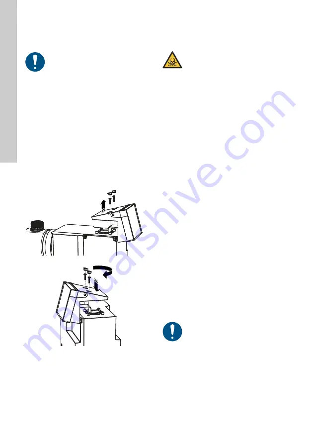
5.1.4 Adjusting the control cube position
The control cube is fitted to the front of the pump on
delivery. It can be turned by 90 ° so that the user can
select to operate the pump from the right or left side.
1. Switch off the power supply.
2. Carefully remove both protective caps on the
control cube using a thin screwdriver.
3. Remove the screws.
– Wrench size: TORX PLUS 15 IP
4. Carefully lift off the control cube only so far from
the pump housing that no tensile stress is
produced on the flat band cable.
– Make sure no liquid enters the housing.
5. Turn the control cube by 90 ° and re-attach.
– Make sure the O-ring is placed correctly.
6. Push down the cube and tighten the screws
using a torque wrench.
– Torque [Nm]: 1.7 (± 0.2)
7. Attach the protective caps observing the correct
orientation.
Fig. 7
Adjusting control cube
5.2 Hydraulic connection
The dosing head may contain water from the factory
check. When dosing media which should not come
into contact with water, another medium must be
dosed beforehand.
Faultless function can only be guaranteed in
conjunction with lines supplied by Grundfos.
The lines used must comply with the pressure limits
as per section
Important information on installation
•
Observe suction lift and line diameter, see
section
.
•
Shorten hoses and pipes at right angles.
•
Ensure that there are no loops or kinks in the
hoses.
•
Keep inlet line as short as possible.
•
Route inlet line up towards the inlet valve.
•
Installing a strainer in the inlet line protects the
entire installation against dirt and reduces the
risk of leakage.
•
Install a pressure-relief valve in the outlet line to
provide protection against impermissibly high
pressure.
•
We recommend the installation of a pulsation
damper downstream the pump:
– for pipe installations.
– for hose installations where the pump is
operated with
≥
75 % of its dosing capacity.
•
Only control variant DDA-FCM and DDA with
DLD:
For discharge quantities < 1 l/h we recommend
the use of an additional spring-loaded valve
(approx. 2 bar) on the outlet side for the safe
generation of the necessary differential pressure.
Install the control cube correctly to ensure
the enclosure class (IP65 / Nema 4X) and
shock protection.
T
M
06
70
51
29
16
WARNING
Chemical hazard
Death or serious personal injury
- Observe the material safety data sheet
of the dosing medium.
- Wear protective clothing (gloves and
goggles) when working on the dosing
head, connections or lines.
Pressure differential between inlet and
outlet side must be at least 1 bar / 14.5 psi.
For control variant FCM and for pumps
with diaphragm leakage detection the
pressure differential between inlet and
outlet side must be at least 2 bar / 29 psi.


