


Eng
lish (US)
46
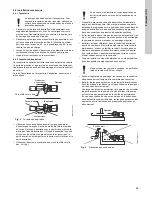
20.2 Digital input
One of the following functions can be selected for the digital
input:
• Normal duty
• Minimum curve
• Maximum curve
• External fault
• Flow switch
• Dry running.
Functional diagram: Input for digital function
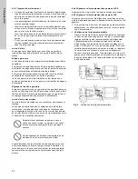
21. External setpoint signal
The setpoint can be remote-set by connecting an analogue signal
transmitter to the input for the setpoint signal (terminal 4).
Fig. 43
Actual setpoint as a product (multiplied value) of
setpoint and external setpoint
Select the actual external signal, 0-10 V, 0-20 mA, 4-20 mA, via
the GO Remote or R100. See section
17.3.3 External setpoint
.
If control mode
uncontrolled
is selected by means of the GO
Remote or R100, the pump can be controlled by any controller.
In control mode
controlled
, the setpoint can be set externally
within the range from the lower value of the sensor measuring
range to the setpoint set on the pump or by means of the GO
Remote or R100.
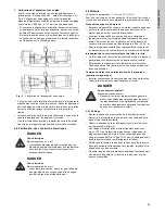
Fig. 44
Relation between the actual setpoint and the external
setpoint signal in control mode controlled
Example:
At a sensor
min
value of 0 psi, a setpoint set of 50 psi
and an external setpoint of 80 % (an 8 V analog signal to Terminal
4 if using an analog signal of 0-10 V), the actual setpoint will be
as follows:
In control mode
uncontrolled
, the setpoint can be set externally
within the range from the min. curve to the setpoint set on the
pump or by means of the GO Remote or R100. Typically the
setpoint is set to 100 % when the control mode is uncontrolled
(see section
17.5 Typical display settings for analog-input E-
pumps
.
Fig. 45
Relation between the actual setpoint and the external
setpoint signal in control mode uncontrolled
Digital function
(terminals 1 and 9) (terminals 9 and 10) (terminals 9 and 11)
Normal duty
Min. curve
Max. curve
External fault
Flow switch
Dry running
T
M
03
86
01
20
07
Q
H
Q
H
Q
H
Q
H
5 s
delay
Q
H
5 s
5 s
delay
Q
H
Setpoint
External setpoint
Actual setpoint
T
M
02
89
8
8
13
0
4
Actual
setpoint
= (setpoint - sensor
min
) x %
external setpoint
+ sensor
min
= (50 - 0) x 80 % + 0
= 40 psi
TM
02 898
8 130
4
0
10 V
0
20 mA
4
20 mA
Actual setpoint
Sensor
max
Setpoint set by means of
control panel, or PC Tool
E-products
Sensor
min
External setpoint signal
Actual
setpoint
0
10 V
0
20 mA
4
20 mA
Actual setpoint
Maximum curve
Setpoint set by means of
control panel, R100 or PC Tool
E-products
Minimum curve
External setpoint signal
Actual
setpoint


