background image

English (GB)

5

3.3 Storage

To prevent water, dust, etc. from entering the pump, all openings 
must be covered until pipes are connected. Apply a suitable 
antirust agent on all machined, non-coated surfaces.
The antirust agent must meet these requirements:
• It must not attack rubber parts.
• It must be easy to remove.
• It must be applied according to the instructions of the 

manufacturer.

If the pump must be stored for more than six months before start-
up, it must be protected against corrosion and damage:
1. Remove the stuffing box packing.
2. Spray the interior part of the pump case and the stuffing box 

with a water-soluble type of antirust agent.

3. If the pump has not been connected to the pipework, cover 

the pump suction and discharge flanges with full natural 
rubber gasket material, and blank off these openings with 
metal blanking flanges. Use at least four bolts for fastening.

4. Cover the opening of the stuffing box with a non-hygroscopic 

tape. The stuffing box gland may be left on the pump shaft, 
but must be wired or otherwise securely fastened in position.

5. Coat all exposed painted surfaces with an antirust agent that 

can be readily removed with a petroleum distillate product.

6. Make sure that all exposed painted surfaces are dry, clean 

and free of grease and other contaminates.

7. Cover the pump with a weather-resistant cover of waterproof 

paper or plastic material to protect it against dirt and dust.

8. Inspect the pump at regular intervals during storage.
9. Rotate the shaft by hand every four to six weeks to prevent 

pitting of the bearings. 

4. Product description

4.1 Fire pump set

The fire pump set consists of a pump, an electric motor and a 
controller. Pump and motor are connected via a flexible coupling. 
All components are adapted to each other and mounted on a 
common base frame ready for installation. The base frame is 
made of steel channel. The controller can also placed separately. 
The fire pump set comes ready for operation.
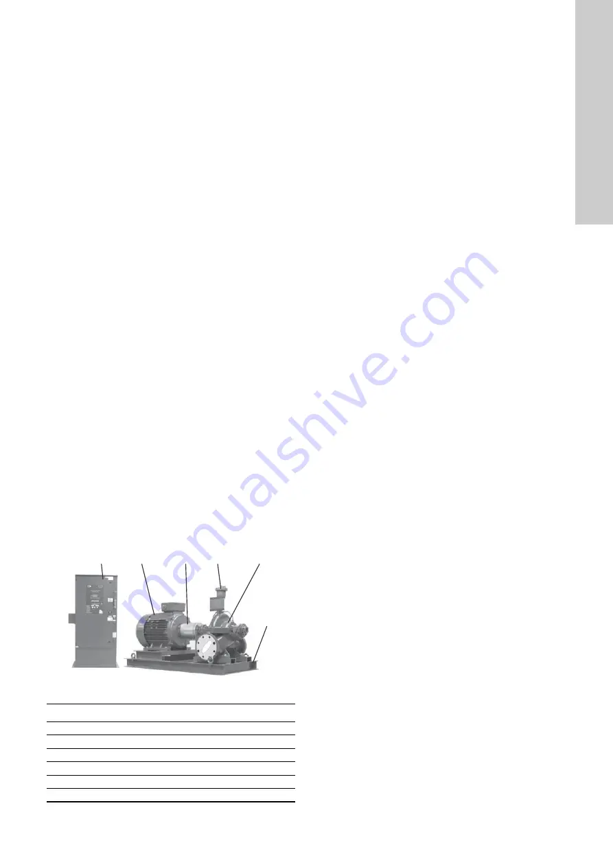
As an example, the most important components of the fire pump 
set are shown in fig. 2. It shows an HSEF fire pump set with a 
Grundfos horizontal split case pump and an electric motor, type 
MMG. Pump and motor are connected by a flexible coupling. 
The controller is installed separately.

Fig. 2

Example of fire pump set

4.2 Pump

The fire pump set comes with a Grundfos HSEF horizontal split 
case pump or a Grundfos DNF end-suction pump. The pumps are 
FM-approved and UL-listed.
The impeller diameter of both pumps can be reduced to 
customise the pump performance to a certain duty point. 
The actual impeller diameter may therefore deviate from the 
standard diameters stated in catalogues, data sheets etc. 
The actual impeller diameter is stated on the pump nameplate.

4.2.1 Split case pump

The Grundfos HSEF horizontal split case pump is a non-self-
priming, single-stage pump. It has inline axial suction and 
discharge ports with PN 10 or PN 16 ANSI flanges. An adapter 
flange from ANSI to DIN is available and must be ordered 
separately. The pumps are equipped with a stuffing box, type 
SNEA or SNFA (see section 

6.1.3 Type key for stuffing box

), and 

with an automatic air release valve making venting unnecessary.

4.2.2 End-suction pump

The pumps are non-self-priming, single-stage Grundfos DNF 
standard pumps with spiral housing. The pumps have an axial 
suction port and a radial discharge port with PN 10 or PN 16 DIN 
flanges.
The DNF pump is equipped with a stuffing box, type SNEA or 
SNFA. See section 

6.1.3 Type key for stuffing box

.

4.3 Motor

The pumps are driven by a 2- or 4-pole Grundfos MMG-E motor 
(15-315 kW) or a Siemens motor (355 kW). All motors are 
produced according to IEC 60034. The rated motor power is 
adapted to the power requirement of the pump. The combinations 
of motors and pumps are shown in section 

19. Dimensions, 

weights and motor data

.

4.4 Controller

4.4.1 General description

The fire pump set is controlled via a Tornatech controller 
especially sized for electric motors driving fire pumps. 
The controller starts the pump automatically and monitors the 
motor. It is FM-approved.
As soon as the sprinklers are activated due to an alarm and water 
is consumed, the pressure in the discharge pipe will be reduced. 
If the pressure becomes lower than the cut-in pressure set on the 
control panel, the pump will start automatically.
Normally, the pump is stopped manually via the controller. 
But automatic stop is also possible if all starting causes have 
returned to normal.
For test run and set-up, manual operation is possible.
The individual controller models differ mainly by starting method 
and power range.

Starting method, model GPA

This model is used where the electricity works or the capacity of 
the power source permits direct-on-line starting.
Full voltage is applied to the motor as soon as the controller 
receives a start command.

Starting method, model GPY

When the controller receives a start command, the motor is 
connected in star. After a time delay, it changes over to delta 
connection with full voltage to the motor windings. This controller 
is of the open transition type. The motor is disconnected from the 
mains during the transition from start (star) to run (delta) mode.

TM

04 51

64 270

9

Pos.

Component

1

Base frame

2

Controller

3

Pump

4

Automatic air release valve

5

Motor

6

Coupling with coupling guard

2

5

6

4

3

1

Summary of Contents for Fire DNF

Page 1: ...Fire DNF Fire HSEF electric Installation and operating instructions GRUNDFOS INSTRUCTIONS...

Page 2: ...EC Member States Machinery Directive 2006 42 EC Standards used EN 12100 1 2003 EN 12100 2 2003 EN 809 1998 Low Voltage Directive 2006 95 EC Standards used EN 60204 1 2006 EN 60439 1 1999 EMC Directiv...

Page 3: ...4 Levelling 17 9 5 Pipework 18 9 6 Bypass 18 9 7 Connection to the pressure sensor 18 9 8 Priming tank and test pipe 18 9 9 Alignment 19 9 10 Separate control cabinet 20 10 Electrical connection 21 1...

Page 4: ...o reduce the risk of fire or electric shock the manufacturer s instructions for selection of overload and short circuit protection must be followed Lifting points for the entire fire pump set Hazadous...

Page 5: ...impeller diameter may therefore deviate from the standard diameters stated in catalogues data sheets etc The actual impeller diameter is stated on the pump nameplate 4 2 1 Split case pump The Grundfo...

Page 6: ...and allows for setting of pressure values See section 5 2 Settings via display Fig 4 Control panel She controller has two DIP switches for settings See section 5 1 Settings via DIP switches The intern...

Page 7: ...ia display Cut in B3 fig 4 This button is used to set the pressure limit for starting the pump It is enabled with a DIP switch See section 5 1 Settings via DIP switches It is also used when setting th...

Page 8: ...an be displayed in PSI P or bar B The display also gives access to the setting menus of the controller See section 5 2 Settings via display 4 4 6 Indicator lights on control panel Four indicator light...

Page 9: ...Pressing these buttons simulates a pressure drop in the system Start delay In systems with several pumps it may be necessary to set a start delay to prevent all motors from starting at the same time...

Page 10: ...scribed below Setting of upper DIP switch Phase reversal reference switch No 6 If indicator light Phase Reversal is on change the DIP switch setting ABC CBA to another setting using a pencil Setting o...

Page 11: ...the previous log To exit the menu do not press any button for more than 30 seconds or press Cut in button B3 for more than 10 seconds Menu 12 event log In this menu the user can view the event log The...

Page 12: ...er placed on the common base frame Example DNF Fire DN F 80 25 260 E A X A A B B Example HSEF Fire HSE F 8 15 323 E B X D A B C Fire Fire system Pump type DN End suction pump HSE Horizontal split case...

Page 13: ...60 60 Hz Example S N E A S Packing type stuffing box N Uncooled stuffing box E With internal barrier fluid F With external barrier fluid A PTFE impregnated fibre packing rings and EPDM O ring in pump...

Page 14: ...AGES MAXIMUM BRAKE HORSEPOWER REQUIRED AT RATED SPEED AT ANY CAPACITY CONDITION 1 3 5 7 9 11 4 6 8 10 12 13 2 34 33 32 31 30 29 28 27 26 25 24 23 22 21 20 19 18 17 16 15 14 13 12 11 10 9 8 7 6 5 4 3 2...

Page 15: ...eplate for the fire pump set See fig 11 8 7 Maximum operating pressure 10 16 or 25 bar The maximum operating pressure is stated on the pump nameplate 8 8 Ambient temperature Minimum ambient temperatur...

Page 16: ...d are one part cement to three parts sand and four parts medium aggregate The concrete foundation must have an absolutely level and even surface Provide the foundation with anchor bolts to fasten to f...

Page 17: ...e borne noise in the pipework only rubber bellows expansion joints Fit the expansion joints both on the suction and the discharge sides The distance from the pump should be at least 1 to 1 1 2 x DN di...

Page 18: ...ssure sensor 1 4 NPTF is on the right side of the controller fig 3 pos 6 Run a hose from the discharge pipe to the pressure sensor Water pipes must be flushed clean before connecting the pressure sens...

Page 19: ...long coupling life This is particularly important with increased motor speed Follow the installation instructions of the coupling manufacturer TM03 2999 5005 Outside diameter of coupling mm Clearance...

Page 20: ...recommended to avoid water accumulation at the controller s feet 7 TM01 8886 0800 Place the foil where needed 8 TM01 8887 0800 Retighten the screws 9 TM01 8888 0800 Check the alignment carefully once...

Page 21: ...erminal 104 106 must be used when connecting a remote control voltage from the other equipment Make sure that the control voltage from other equipment and that from control relay CR10 are compatible F...

Page 22: ...uttons START and STOP 10 Simulate a power failure by turning the circuit breaker to OFF and check if the circuit connected to terminals PowAv is reacting properly 11 Simulate phase reversal by pressin...

Page 23: ...ndle back to OFF and press STOP button A3 fig 3 pos 3 12 3 Test run To start a test run open the isolating valve to the test pipe and press buttons Cut in B3 and Cut out B2 fig 4 The pump runs for ten...

Page 24: ...hermal paper and be correctly oriented The following operations must be followed to replace the paper 1 Unscrew the axle and remove the empty roll 2 On the printer open the top cover to get access to...

Page 25: ...e desired results To set the leakage rate of the stuffing box remove the protecting guards of the shaft on both sides This gives access to the setting screw See service instructions Bearing lubricatio...

Page 26: ...pipe has been installed according to section 9 5 Pipework c Impeller out of balance Clean the impeller d Inner pump parts worn Replace defective parts e Pump stressed by the pipework Install the pump...

Page 27: ...ce technician can prepare and provide the appropriate spare parts Please obtain the technical data for the system from the nameplate 17 Warranty The warranty is governed by the framework of our genera...

Page 28: ...75 2220 x 701 x 1320 1050 525 MMG 280M E 90 2271 x 701 x 1320 1096 590 HSEF 5 8 MMG 200LA E 30 2010 x 701 x 1320 669 6 5 283 283 143 248 MMG 200LB E 37 2010 x 701 x 1320 692 270 HSEF 5 11 MMG 225M E 4...

Page 29: ...5 525 MMG 280M E 90 1728 x 701 x 842 891 590 HSEF 5 12 MMG 280M E 90 1733 x 701 x 891 999 6 5 302 390 257 590 MMG 315S E 110 1943 x 853 x 976 1479 1050 MMG 315M E 132 2023 x 853 x 976 1591 1150 HSEF 6...

Page 30: ...0M E 55 2280 x 701 x 1320 1195 447 MMG 280S E 75 2355 x 701 x 1472 1344 554 HSEF 8 17 MMG 280S E 75 2399 x 701 x 1472 1400 10 8 353 302 458 554 MMG 280M E 90 2449 x 701 x 1472 1447 600 MMG 315S E 110...

Page 31: ...E 55 1775 x 701 x 915 1037 447 MMG 280S E 75 1805 x 701 x 942 1138 554 HSEF 8 17 MMG 280S E 75 1844 x 701 x 994 1194 10 8 353 302 458 554 MMG 280M E 90 1894 x 701 x 994 1241 600 MMG 315S E 110 2028 x...

Page 32: ...80M E 90 2980 154 89 7 2 HSEF 5 12 MMG 280M E 90 3 x 380 415 660 690 Y 2980 154 89 7 2 MMG 315S E 110 2980 188 108 7 2 MMG 315M E 132 2980 222 128 7 5 HSEF 6 10 MMG 280S E 75 3 x 380 415 660 690 Y 297...

Page 33: ...74 7 4 HSEF 8 15 MMG 225M E 45 3 x 380 415 660 690 Y 1480 78 45 7 5 MMG 250M E 55 1480 95 55 7 5 MMG 280S E 75 1480 128 74 7 4 HSEF 8 17 MMG 280S E 75 3 x 380 415 660 690 Y 1480 128 74 7 4 MMG 280M E...

Page 34: ...34...

Page 35: ...22 Japan Phone 81 35 448 1391 Telefax 81 35 448 9619 Korea GRUNDFOS Pumps Korea Ltd 6th Floor Aju Building 679 5 Yeoksam dong Kangnam ku 135 916 Seoul Korea Phone 82 2 5317 600 Telefax 82 2 5633 725 L...

Page 36: ...1739 The name Grundfos the Grundfos logo and be think innovate are registered trademarks owned by Grundfos Holding A S or Grundfos A S Denmark All rights reserved worldwide Copyright Grundfos Holding...

Reviews: