32
16. Slide the pump shaft 51 towards the pump
housing until it stops,with the spacer jammed
between the impeller and the housing. This
ensures the correct space between the housing
and the impeller.
17. Tighten the hexagon head screws 9 of the
clamp-connection crosswise, attempting to
ensure the tension rings remain as parallel as
possible.
Torque:
first circuit with 3,5 lbf ft (5 Nm).
second circuit with 6 lbf ft (8 Nm).
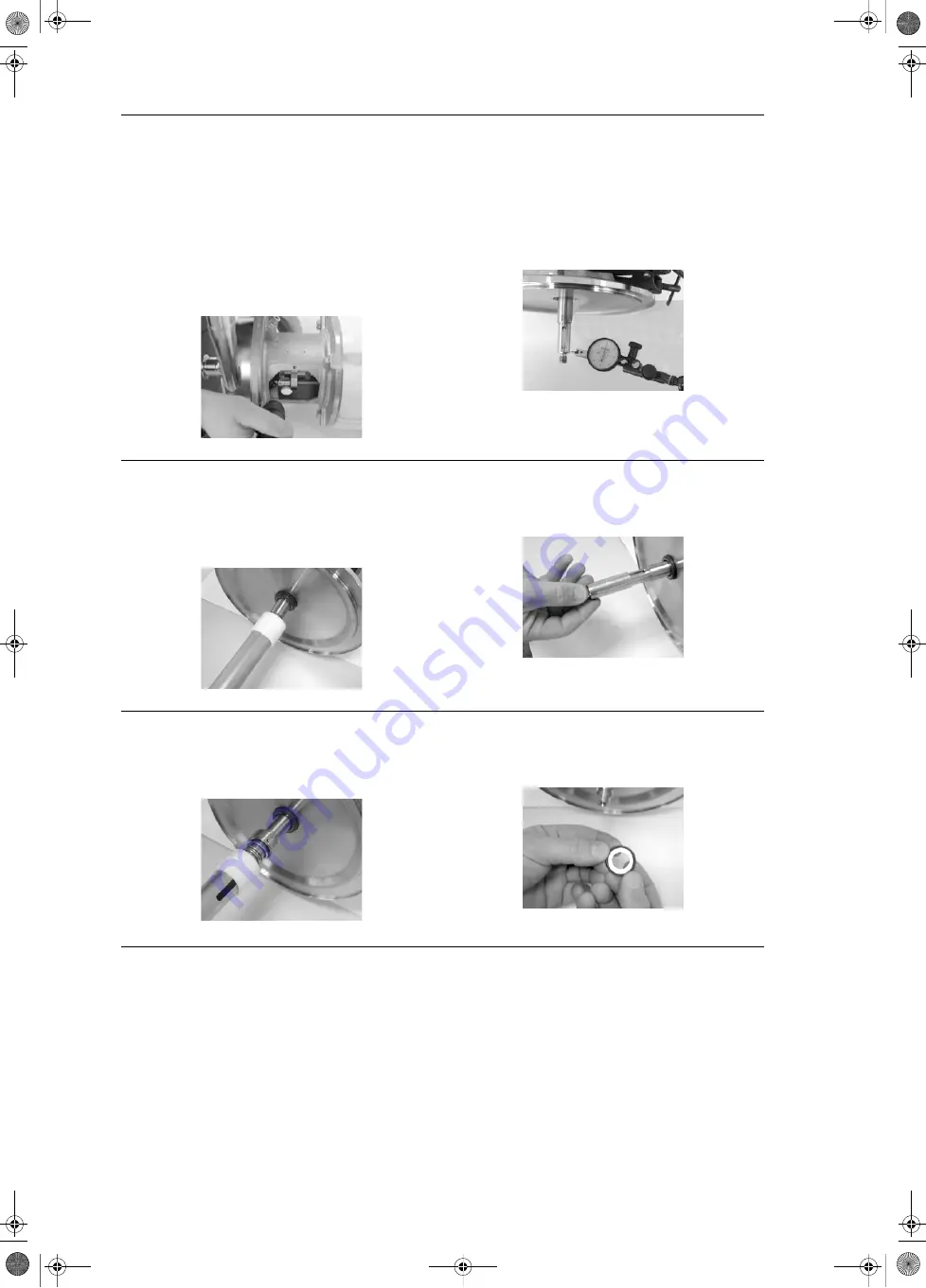
Fig. 39
Tighten hexagon head screws
18. Remove clamp ring 92a/b and pump housing 6.
Remove impeller nut 67, O-ring 66, spacer
device, impeller 49 and seal spacer 61.
19. Check concentricity of pump shaft 51.
Maximum permitted deviation: 0.002 inch
(0,05mm).
If the limit is exceeded: Disassemble clamp
connection and assemble it again or use an
appropriate tool to adjust (soft mallet).
Fig. 40
Sensing head
20. Spray clean water onto the pump shaft 51 to
assist the seal assembly.
21. Push the stationary ring of the mechanical seal
105 into the seat of the motor stool 2.
Use installation sleeve from Grundfos FB Pump
tool kit (pos. 6 or 7, fig. 55) to do this.
Fig. 41
Stationary mechanical seal
22. Slide the assembly sleeve from Grundfos FB
Pump tool kit (pos. 1, fig. 55) onto the shaft
extension.
23. Spray the assembly sleeve with clean water.
Fig. 42
Assembly sleeve
24. Spray clean water onto the pump shaft 51.
25. Slide the rotary part of the mechanical seal 105
over the assembly sleeve and onto the pump
shaft 51.
Remove assembly sleeve from the shaft.
Fig. 43
Rotary mechanical seal
26. Insert the O-ring seal spacer 109 into the seal
spacer 61.
Applies to the open mechanical seal only
(see fig. 11 on page 25).
Fig. 44
Seal Spacer


