


Instructions
EZ Boost
TM
System
POWER
PE
PUMP
PE
L
N
Brown
Black
4
1
3
2
SENSOR
5 6 7
+24V
IN
GN
D
L1
L N
L2
For 230V
6.3.3. NOTES:
Connect one PE terminal to the green ground lead from the
pump and one to the ground lead from the main power
supply. Each PE terminal must be connected to its own
ground lead.
Maximum wire size of the cables to be connected to EZ
Boost controller is 10 AWG.
6.4. Positioning the pressure sensor
Pressure losses often cause inconvenience to the user.
The EZ Boost controller keeps the pressure constant in the
place where the pressure sensor is positioned (see EZ Boost
System Diagram on page 16). In the diagram tap 1 is placed
close to the pressure sensor. Therefore, the pressure will be
kept nearly constant at tap 1, as the friction loss is small.
At the shower and tap 2, the friction loss is greater. This, of
course, depends on the piping. Therefore, it is recommend-
ed that the pressure sensor be positioned as close to the
places of consumption as possible. The maximum shielded
cable length for the sensor must not exceed 1600 feet.
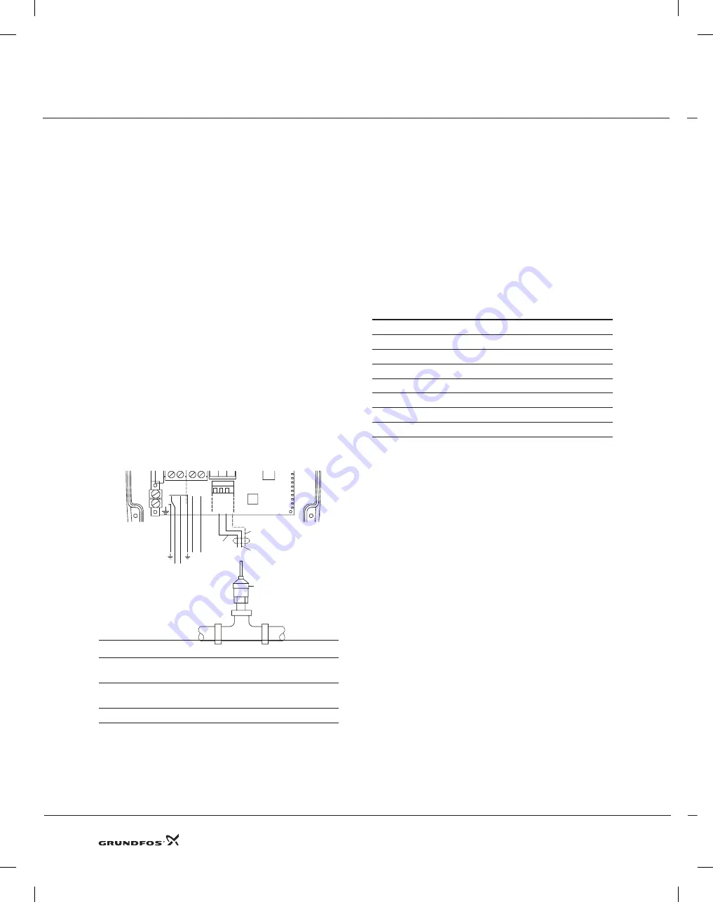
6.4.1 Connection of the pressure sensor
SENSOR, terminals 5, 6 and 7:
Terminals 5, 6 and 7 (SENSOR) are used for the pressure
sensor.
Pos.
Description
1
Standard pressure 24 VDC, brown
lead, terminal 5.
2
Standard pressure sensor. Input signal, black
lead, terminal 6.
3
Standard pressure sensor. Braid, terminal 7.
Sensor signals:
The pressure sensor to be conected provides a 4-20 mA
signal (factory setting).
6.5. Diaphragm Pressure Tank
The EZ Boost controller is designed to work with a 2 gal.
diaphragm tank. Install a diaphragm tank to insure that the
BMQE will shut off at zero flow. The diaphragm tank must
be installed at some point between the BMQE pump and
the pressure sensor.
6.5.1 Pre-charge Pressure Setting
The pre-charge pressure of the diaphragm tank must be set
to 70% of the pressure setting in order to use the tank to
the limit of its capacity.
Use the values in the following table. Pre-charge pressure is
measured with 0 PSI in the pipeline:
Setting (PSI)
Pre-charge pressure (PSI)
40
28
50
35
60
42
70
49
80
56
90
63
100
70
Note:
If the pre-charge pressure is higher than the pres-
sure setting, the system will have difficulty controlling the
pressure.
If the user wants to adjust the pressure without chang-
ing the pre-charge pressure of the diaphragm tank, the
pre-charge pressure must be equal to the lowest pressure
setting used. Failure to follow this instruction will increase
pressure fluctuations.
6.6. Pressure Relief Valve
In order to provide protection against the possibility of over
pressurization, a pressure relieve valve may be installed
down stream of the BMQE. If a relief valve is installed, it
is recommended that its discharge be plumbed into an
appropriate drainage point.
6.7. Liquid filling and BMQE pump venting
The BMQE is filled with water through the suction port by
the water in the piping system.
1. The BMQE should be installed with the air relief vent
in the 12 o’clock position when installed horizontally
and when installed in the vertical position the air vent
must be at the top of the unit.
2. Loosen the air vent screw in the BMQE pump.
3. Fill the BMQE with water until it starts running out of
the vent hole.
4. Tighten the air vent screw.
8


