


5.1.2 Functional principle of the pump
DMX pumps are reciprocating displacement pumps with electric motor and a mechanical dia-
phragm.
•
Alternating strokes cause the diaphragm to increase and decrease the size of the dosing
chamber and by that draw in and force out dosing medium through the inlet and outlet
valves.
•
The dosing strokes are generated by an eccentric, which moves the diaphragm by means of
a tappet.
•
The suction strokes are activated by the return movement of the spring.
•
The stroke volume and thus the dosing flow can be adjusted by adjusting the stroke length.
Dosing flow control
•
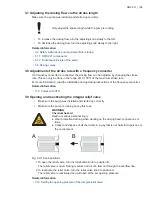
Flow control via the stroke length: The flow can be controlled either by turning the stroke-
length adjusting knob manually, or by means of an optional servomotor. The volume of each
stroke is increased or decreased, the stroke rate remains constant.
•
Flow control via frequency converter (VFD): The flow can be controlled via an integrated or
external frequency converter. The volume of each stroke remains constant, the stroke rate is
increased or decreased.
•
Flow control via AR control unit: The flow of DMX pumps with AR control unit can be control-
led by adjusting the interval between strokes. This is done via analog or pulse signals or by
manually adjusting the stroke frequency.
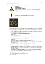
5.1.3 AR control unit
The AR control unit offers various operating modes, control functions and monitoring functions.
The AR control unit has an IP65 plastic housing. The AR control unit is available for pumps with
single-phase motors.
Observe the installation and operating instructions for the AR control unit.
Related information
• http://net.grundfos.com/qr/i/91834764
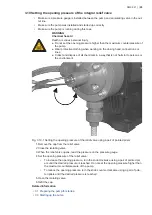
5.1.4 Functional principle of the integral relief valve
Some dosing head variants have an integral relief valve. The opening pressure of the integral re-
lief valve is factory-set to the maximum counterpressure stated on the pump nameplate. During
operation, the opening pressure depends on various factors, such as the flow, the stroke frequen-
cy or the counterpressure in the dosing system. The integral relief valve can be adapted to the
local conditions.
•
If the pressure in the dosing head rises above the set opening pressure, the integral relief
valve will open. The dosing medium will flow through the overflow line, and it can be re-
turned into the dosing tank.
•
The integral relief valve will protect the outlet side from an excessive pressure build-up by
the pump. The integral relief valve will also protect the pump if the outlet valve is dirty or
blocked.
•
The integral relief valve can be opened manually. This function can be used to deaerate the
dosing head and the inlet line.
Related information
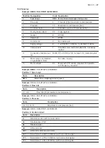
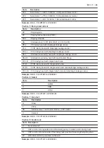
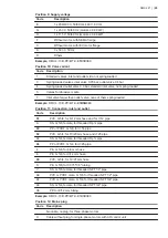
• 5.3.2 Type key
• 3.10 Setting the opening pressure of the integral relief valve
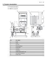
DMX 221 | |
24


