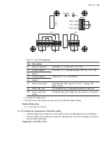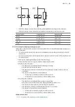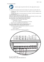
ALARM
ON
MBS
GND / white
+5V / yellow
OUT / green
REL 1
REL 2
1L
2N
3PE
4PE
5N
6
7
D2
D5
8
9
10
S2
S1
T1
C1
T2
C2
Fig. 11.1.3.2-1 Wiring diagram
Pos. Description
T1
Power connection
Terminals 1, 2, 3: 230 V AC / 115 V AC
C1
Contact output 1
Terminals 5, 6, 7: potential-loaded, 230 V AC / 115 V AC
S1
Relay 1
C2
Contact output 2
Terminals 8, 9, 10: potential-free
S2
Relay 2
T2
Sensor connection
Terminals GN (OUT / green), YE (+5 V / yellow), WH
(GND / white)
D2
Alarm LED (red)
The LED lights up if a diaphragm leakage is detected.
D5
Sensor LED (red/
green)
The LED shows green light when the sensor is connected.
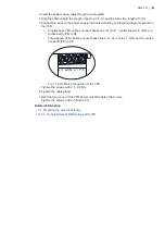
13. Tighten the cable gland.
14. Fit the cover to the electronic unit and fasten it with the plastic screws.
Related information
• 11.1.3 Electrical connection
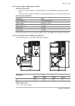
11.1.3.3 Interference suppression of inductive loads
•
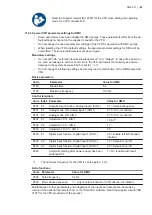
Inductive loads on the electronic unit for optical sensor will damage relays and contactors.
•
Inductive loads on the electronic unit can be eliminated by means of a suppressor circuit as
the one described below.
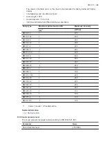
Suppressor circuit DC or AC
DMX 221 | |
58

