


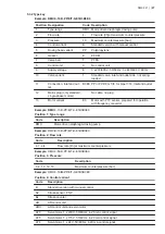

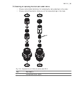
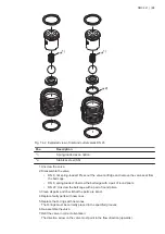
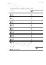

5.3.2 Type key
Example: DMX 4-10 B-PP/E/T-X-E1B3B3E0
Position Designation
Code Description
1
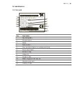
Type range
DMX Motor-driven diaphragm dosing pump
2
Flow rate
4-
Flow rate [l/h] at maximum counterpressure
3
Pressure
10
Maximum counterpressure [bar]
4
Control variant
B-
Standard version with manual control
5
Dosing head variant
PP
Polypropylene
6
Gasket
E
EPDM
7
Valve ball
T
PTFE
8
Control unit
X
No control unit
9
Supply voltage
E
3 x 230/400 V, 50/60 Hz; 3 x 440/480 V, 60 Hz
10
Valve variant
1
Standard valve, inlet and outlet side, not spring-
loaded
11
Connection, inlet and out-
let
B3B3 PP or PVDF, G 5/8, for pipe
∅
16, inlet and outlet
12
Mains plug (only standard,
single-phase motors)
No cable, no plug
13
Motor variant
E0
Motor with PTC sensor, prepared for operation
with frequency converter
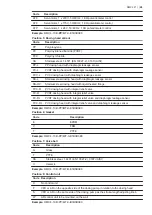
Example: DMX
4-10 B-PP/E/T-X-E1B3B3E0
Position 1: Type range
Code
Description
DMX
Motor-driven diaphragm dosing pump
Example:
DMX
4
-10 B-PP/E/T-X-E1B3B3E0
Position 2: Flow rate
Code
Description
4, 7, etc.
Flow rate [l/h] at maximum counterpressure
Example:
DMX 4-
10
B-PP/E/T-X-E1B3B3E0
Position 3: Pressure
Code
Description
3, 4, 10, 12, 16
Maximum counterpressure [bar]
Example:
DMX 4-10
B
-PP/E/T-X-E1B3B3E0
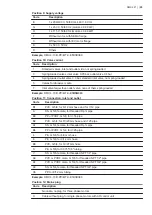
Position 4: Control variant
Code
Description
B
Standard version with manual control
S2
Stroke sensor, PNP
Bx
Stroke counter
AR
AR control unit
ARX
AR control unit and servomotor
AT3
Servomotor, 1 x 230 V, 50/60 Hz, 4-20 mA control signal
AT5
Servomotor, 1 x 115 V, 50/60 Hz, 4-20 mA control signal
AT4
Servomotor, 1 x 24 V, 50/60 Hz, 4-20 mA control signal
DMX 221 | |
27


