E
thernet
P
anel
Hardware EthernetPanel
20
DVS
48961 V3.0
© 2010 by Grossenbacher Systeme AG
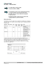
The CAN interface is NOT isolated.
The max. baud rate is 1MBit/s.
The terminating resistor must be implemented externally,
e.g. in the connector, and is not part of the device.
The CAN connector is not provided with a supply for
third-party devices.
A detailed description of the wiring is provided in the
“Codesys Soft-PLC” system description
Wiring instructions
The stations on the bus system are connected via fieldbus lines complying
with ISO 11898. The cables must accordingly have the following electrical
characteristics:
Parameter Abbreviation Unit Value Value Value Note
min.
nom.
max.
Impedance Z
Ω
108
120
132
Measured between two
signal lines
Specific
resistance
m
Ω
/m 70 For
the
receiver
module, the differential
voltage on the bus
cable depends on cable
resistance between it
and the sender
Cable delay
ns/m
5
The mininum delay
between to points on
the bus is 0. The
maximum delay is
determined by the bit
timing and the delays of
the sender and receiver
circuits
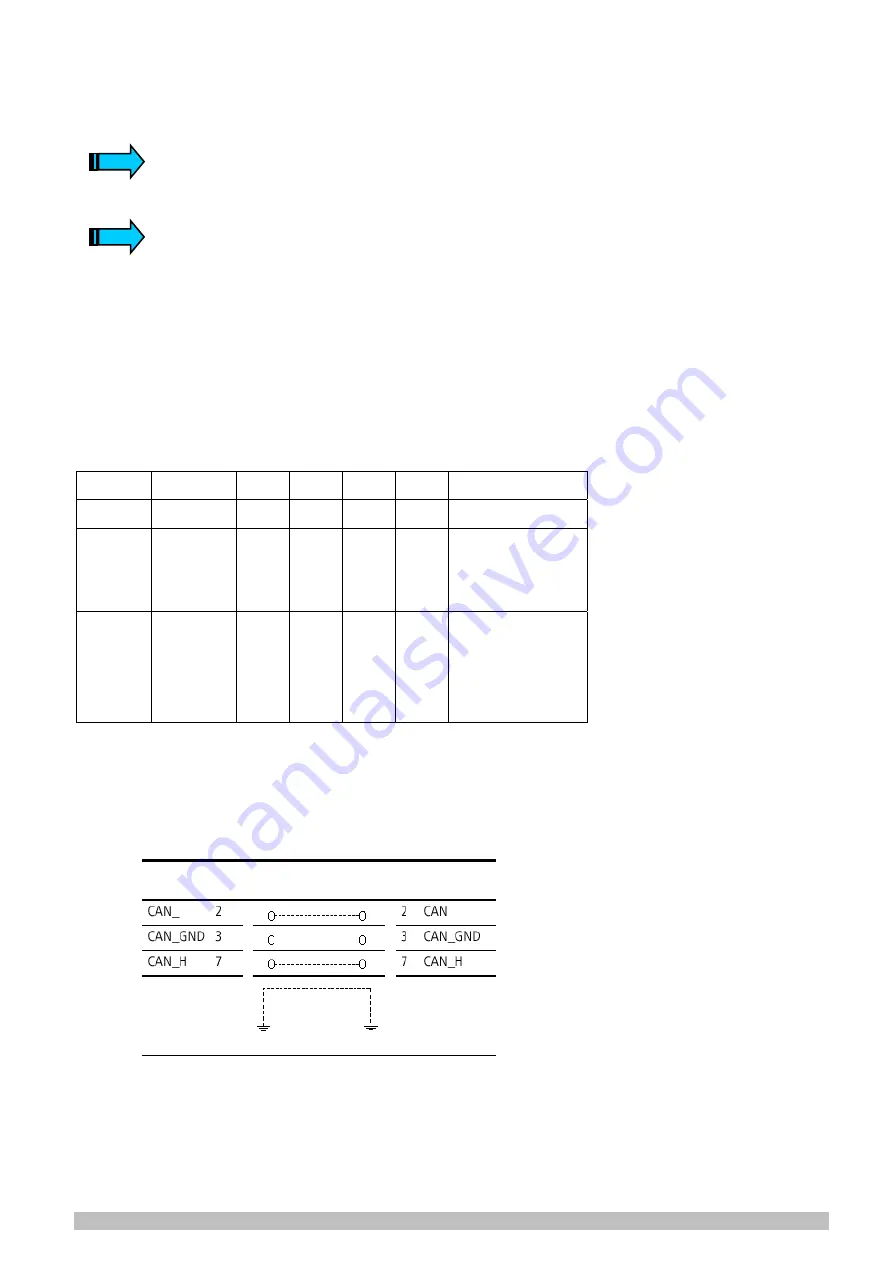
The figure shows the minimum wiring with shielding between two bus
stations with the Sub-D connector as an example. A bus terminating resistor
(120 Ohm between Pin 2 and Pin 7 of the Sub-D connector) must be
connected at the beginning and the end of each CAN bus. Do not swap
around the two signal wires!
Protective ground
Shield
Interface 1
Protective ground
DVS 48961-V4.0
Summary of Contents for 50 81 332
Page 52: ...DVS 48961 V4 0...


