E
thernet
P
anel
Hardware EthernetPanel
© 2010 by Grossenbacher Systeme AG DVS 48961 V3.0
19
5.8 C
ONNECTION FOR
COM1
SERIAL INTERFACE
(RS232)
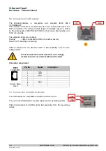
The serial Interface COM1 is PC-compatible. This interface is not isolated.
The GND connection is implemented directly on the housing potential (
Î
Section 11).
Connector
Pin No.
Signal
Description
1 DCD
2
RXD
3
TXD
4
DTR
Opional
5VDC
5
GND
6
DSR
7
RTS
Connector
9pole
8 CTS
SubD
9 RI
Opional
5VDC
Opionally it is possible to provide 5V/0.5A on Pin 4 or 9.
This 5V power supply is short-circuit-proof.
The configuration can only be factory made.
Cables connected to the programming interface (Ethernet or serial) must be
laid separately from the low-voltage cables.
To ensure disturbance-free operation, it is strongly
recommended to use cables with shield.
5.9 CAN
INTERFACE
The communication interface is defined in accordance with the CiA CAN
Specification V2.0 part B. The fully-integrated CAN unit supports the sending
and receiving of frames with an 11-bit identifier. The type of configuration
selected depends on the software protocol. The baud rate can be selected in
a wide range, and only the standard CiA baud rates are implemented.
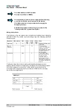
CAN connector
Sub-D 9 Pole male
Connect
or
Pin No.
Assignme
nt
Function
1
-
2 CAN
LOW
Negative data signal
3
GND
Signal Ground (ground potential)
4 -
5 -
6
GND
Signal Ground (ground potential)
7 CAN
HIGH
Positive data signal
8 -
9 -
Case
Case
Cable
shield
1 2 3 4 5
6 7 8 9
5
5
9
4
8
3
7
2
6
1
5
9
4
8
3
7
2
6
1
1 2 3 4 5
6 7 8 9
6
DVS 48961-V4.0
Summary of Contents for 50 81 332
Page 52: ...DVS 48961 V4 0...


