


Improper connection of the equipment-grounding
wire can result in a risk of electric shock. The
wire with green insulation (with or without yellow
stripes) is the equipment-grounding wire. If repair
or replacement of the power cord or plug is nec-
essary, do not connect the equipment-grounding
wire to a live (current carrying) terminal.
Check with a qualified electrician or service per-
sonnel if you do not understand these grounding
requirements, or if you are in doubt about whether
the tool is properly grounded. If you ever notice
that a cord or plug is damaged or worn, discon-
nect it from power, and immediately replace it with
a new one.
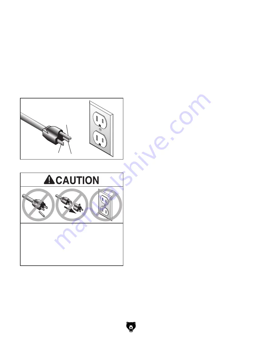
SHOCK HAZARD!
Two-prong outlets do not meet the grounding
requirements for this machine. Do not modify
or use an adapter on the plug provided—if
it will not fit the outlet, have a qualified
electrician install the proper outlet with a
verified ground.
This machine MUST be grounded. In the event
of certain malfunctions or breakdowns, grounding
reduces the risk of electric shock by providing a
path of least resistance for electric current.
This machine is equipped with a power cord that
has an equipment-grounding wire and a grounding
plug. Only insert plug into a matching receptacle
(outlet) that is properly installed and grounded in
accordance with all local codes and ordinances.
DO NOT modify the provided plug!
We do not recommend using an extension cord
with this machine. If you must use an extension
cord, only use it if absolutely necessary and only
on a temporary basis.
Extension cords cause voltage drop, which can
damage electrical components and shorten motor
life. Voltage drop increases as the extension cord
size gets longer and the gauge size gets smaller
(higher gauge numbers indicate smaller sizes).
Any extension cord used with this machine must
be in good condition and contain a ground wire
and matching plug/receptacle. Additionally, it must
meet the following size requirements:
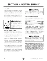
Figure 4. Typical 5-15 plug and receptacle.
Grounding Pin
Neutral Hot
5-15 PLUG
GROUNDED
5-15 RECEPTACLE
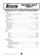
Model T32304 (Mfd. Since 02/21)
-11-
Extension Cords
Grounding & Plug Requirements
Minimum Gauge Size ........................... 16 AWG
Maximum Length (Shorter is Better)....... 50 ft.
Summary of Contents for T32304
Page 52: ......