Grizzly T28360 Owner'S Manual Download Page 9

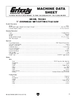
Model T28360 (Mfd. Since 11/18)

-7-

ELECTRICAL EQUIPMENT INJURY RISKS. 

You can be shocked, burned, or killed by touching 

live electrical components or improperly grounded 

machinery. To reduce this risk, only allow qualified 

service  personnel  to  do  electrical  installation  or 

repair work, and always disconnect power before 

accessing or exposing electrical equipment.

DISCONNECT POWER FIRST.  Always  discon-

nect  machine  from  power  supply  BEFORE  mak-

ing  adjustments,  changing  tooling,  or  servicing 

machine.  This  prevents  an  injury  risk  from  unin-

tended  startup  or  contact  with  live  electrical  com-

ponents.

EYE PROTECTION. Always wear ANSI-approved 

safety glasses or a face shield when operating or 

observing  machinery  to  reduce  the  risk  of  eye 

injury or blindness from flying particles. Everyday 

eyeglasses are NOT approved safety glasses.

OWNER’S MANUAL. Read and understand this 

owner’s manual BEFORE using machine. 

TRAINED OPERATORS ONLY. Untrained oper-

ators  have  a  higher  risk  of  being  hurt  or  killed. 

Only  allow  trained/supervised  people  to  use  this 

machine.  When  machine  is  not  being  used,  dis-

connect  power,  remove  switch  keys,  or  lock-out 

machine to prevent unauthorized use—especially 

around children. Make your workshop kid proof!

DANGEROUS ENVIRONMENTS. Do  not  use 

machinery in areas that are wet, cluttered, or have 

poor lighting. Operating machinery in these areas 

greatly increases the risk of accidents and injury.

MENTAL ALERTNESS REQUIRED. Full mental 

alertness is required for safe operation of machin-

ery. Never operate under the influence of drugs or 

alcohol, when tired, or when distracted.

For Your Own Safety, Read Instruction 

Manual Before Operating This Machine

The purpose of safety symbols is to attract your attention to possible hazardous conditions. 

This manual uses a series of symbols and signal words intended to convey the level of impor-

tance of the safety messages. The progression of symbols is described below. Remember that 

safety messages by themselves do not eliminate danger and are not a substitute for proper 

accident prevention measures. Always use common sense and good judgment.

Indicates a potentially hazardous situation which, if not avoided, 
MAY result in minor or moderate injury. It may also be used to alert 
against unsafe practices.

Indicates a potentially hazardous situation which, if not avoided, 
COULD result in death or serious injury.

Indicates an imminently hazardous situation which, if not avoided, 
WILL result in death or serious injury.

Alerts the user to useful information about proper operation of the 
machine to avoid machine damage.

NOTICE

Safety Instructions for Machinery

SECTION 1: SAFETY

Summary of Contents for T28360

Page 1: ...G NO PORTION OF THIS MANUAL MAY BE REPRODUCED IN ANY SHAPE OR FORM WITHOUT THE WRITTEN APPROVAL OF GRIZZLY INDUSTRIAL INC TKESAB19480 PRINTED IN CHINA V1 01 19 MODEL T28360 7 OVERHEAD WET CUTTING TILE...

Page 2: ...g grinding tool integrity and the usage of personal protective equipment The manufacturer will not be held liable for injury or property damage from negligence improper training machine modifications...

Page 3: ...ection 14 Test Run 15 SECTION 4 OPERATIONS 16 Operation Overview 16 Cutting Tips 17 Making Miter Cuts 17 Making Bevel Cuts 17 Installing Changing Blade 18 SECTION 5 ACCESSORIES 19 SECTION 6 MAINTENANC...

Page 4: ...ade every effort to be exact with the instruc tions specifications drawings and photographs in this manual Sometimes we make mistakes but our policy of continuous improvement also means that sometimes...

Page 5: ...hown below to better understand the instructions in this manual Slide Handle Bevel Lock Knob Bevel Gauge ON OFF Switch Locking Miter Gauge Drain Plug Table Blade Table Fence To reduce your risk of ser...

Page 6: ...f this machine Understanding these items and how they work will help you understand the rest of the manual and stay safe when operating this machine To reduce your risk of serious injury read this ent...

Page 7: ...21 x 14 in Must Ship Upright Yes Electrical Power Requirement 120V Single Phase 60 Hz Full Load Current Rating 6 64A Minimum Circuit Size 15A Connection Type Cord Plug Power Cord Included Yes Power Co...

Page 8: ...r Coated Other Specifications Country of Origin China Warranty 1 Year Approximate Assembly Setup Time 15 min Serial Number Location ID Label ISO 9001 Factory Yes ISO 9001 Factory Yes Certified by a Na...

Page 9: ...d proof DANGEROUS ENVIRONMENTS Do not use machinery in areas that are wet cluttered or have poor lighting Operating machinery in these areas greatly increases the risk of accidents and injury MENTAL A...

Page 10: ...moving parts or flying debris Make sure they are properly installed undamaged and working correctly BEFORE operating machine FORCING MACHINERY Do not force machine It will do the job safer and better...

Page 11: ...HAZARDS Electrocution may occur due to water entering electrical connec tions GFCI Ground Fault Circuit Interrupter will interrupt circuit if excessive amp draw is detected Always connect this machine...

Page 12: ...n undersized circuit To reduce the risk of these hazards avoid over loading the machine during operation and make sure it is connected to a power supply circuit that meets the requirements in the foll...

Page 13: ...onger and the gauge size gets smaller higher gauge numbers indicate smaller sizes Any extension cord used with this machine must be in good condition and contain a ground wire and matching plug recept...

Page 14: ...packing materials shipped with this machine The following items are needed but not included for the setup assembly of this machine Description Qty Safety Glasses 1 Phillips Screwdriver 2 1 Needed for...

Page 15: ...nches may require additional rein forcement to support the weight of the machine and workpiece materials Consider anticipated workpiece sizes and addi tional space needed for auxiliary stands work tab...

Page 16: ...into the power receptacle Drip Loop Figure 8 Connecting to power with a drip loop Disconnecting Power Figure 9 Disconnecting power Turn the machine OFF Grasp the plug and pull it completely out of th...

Page 17: ...or unexpect ed results that can lead to serious injury death or machine property damage Serious injury or death can result from using this machine BEFORE understanding its controls and related safety...

Page 18: ...chine is used during operation so the machine controls components discussed later in this manual are easier to understand Due to the generic nature of this overview it is not intended to be an instruc...

Page 19: ...ing Bevel Cuts This machine will make bevel cuts between 0 and 45 degrees Limit stops on the end brackets pro vide quick settings at 0 degrees and 45 degrees To make a bevel cut 1 DISCONNECT MACHINE F...

Page 20: ...s not an option 5 Hold arbor in place with arbor wrench see Figure 14 then loosen and remove arbor with socket wrench see Figure 14 Item s Needed Qty Tile Saw Blade Grizzly Part T30312 1 Phillips Head...

Page 21: ...s precision angled cuts and circular hole cuts with equal ease The 3 in 1 cutter features an extra heavy duty base for excellent stability while cutting A miter gauge style tile stop adjusts to 45 deg...

Page 22: ...Protector 4 T20502 Face Shield Crown Protector 7 T20503 Face Shield Window T20451 Kirova Clear Safety Glasses T20452 Kirova Anti Reflective S Glasses T20456 DAKURA Safety Glasses Figure 20 Assortment...

Page 23: ...pump with clean water Clean and lubricate guide rods Check wear on saw blade and dress or replace as necessary Monthly Check Remove support frame and thoroughly clean water tray Schedule The only comp...

Page 24: ...e or clog at pump 4 Use larger gauge or shorter extension cord 5 Clean motor let cool and reduce workload 6 Test repair replace Machine has vibration or noisy operation 1 Motor or component is loose 2...

Page 25: ...ee Figure 23 To reduce risk of shock or accidental startup always disconnect machine from power before adjustments maintenance or service 3 Slide saw carriage along length of guide rods looking for sm...

Page 26: ...bevel limit stops which align the saw carriage to the table and allow it to be quickly set to 45 and return to 0 If fences are parallel no adjustment is needed If fences are not parallel proceed to St...

Page 27: ...d of table and repeat Step 4 If table and blade are perpendicular at both ends of table no adjustment is needed If table and blade are not perpendicular at one or both ends of the table proceed to Ste...

Page 28: ...edge where the square meets the blade Figure 28 Combination square placed against table and blade Combination Square 5 Move carriage to opposite end of table and repeat Step 4 If table and blade are...

Page 29: ...t at the time of printing but may not match your machine If you find this to be the case use the wiring diagram inside the motor junction box CAPACITORS INVERTERS Some capacitors and power inverters s...

Page 30: ...Capacitor JP 900N 0 14A 60HZ 120VAC 30 UF 250VAC When servicing wiring take care not to damage rubber gasket between motor and switch Otherwise internal wiring may be exposed to water causing machine...

Page 31: ...2 10 13 14 15 16 19 18 17 20 14 21 22 23 19 17 24 26 1 96 97 25 1 25 2 25 4 25 3 26 2 26 4 26 3 26 25 105 Table Tray SECTION 9 PARTS We do our best to stock replacement parts when possible but we cann...

Page 32: ...PT28360008 HEX NUT M6 1 25 2 PT28360025 2 ROLL PIN 6 X 10 9 PT28360009 LOCK WASHER 6MM 25 3 PT28360025 3 GUIDE 10 PT28360010 FENDER WASHER 6MM 25 4 PT28360025 4 KNOB BOLT M6 1 X 6 D38 6 LOBE 11 PT2836...

Page 33: ...0 31 34 34 31 30 35 36 37 38 39 40 43 44 41 42 45 41 46 47 48 49 50 51 52 53 45 54 55 50 56 57 43 58 47 41 46 59 44 45 41 60 61 62 63 64 65 66 69 70 56 71 72 68 74 75 76 104 77 78 79 80 81 82 83 84 85...

Page 34: ...KNOB BOLT M10 1 5 X 30 12 X 28 4 LOBE 83 PT28360083 HEX BOLT M5 8 X 10 45 PT28360045 FENDER WASHER 10MM 84 PT28360084 CAPACITOR BRACKET 46 PT28360046 POINTER 85 PT28360085 LOCK NUT M5 8 47 PT28360047...

Page 35: ...e the owner of this machine MUST replace it in the original location before resuming operations For replacements contact 800 523 4777 or www grizzly com REF PART DESCRIPTION REF PART DESCRIPTION 201 P...

Page 36: ......

Page 37: ...metalworker ____ 0 2 Years ____ 2 8 Years ____ 8 20 Years ____20 Years 6 How many of your machines or tools are Grizzly ____ 0 2 ____ 3 5 ____ 6 9 ____10 7 Do you think your machine represents a good...

Page 38: ...LINE FOLD ALONG DOTTED LINE GRIZZLY INDUSTRIAL INC P O BOX 2069 BELLINGHAM WA 98227 2069 Place Stamp Here Name_______________________________ Street_______________________________ City______________S...

Page 39: ...shall be tried in the State of Washington County of Whatcom We shall in no event be liable for death injuries to persons or property or for incidental contingent special or consequential damages arisi...

Page 40: ......

Reviews: