


Model T28360 (Mfd. Since 11/18)
-25-
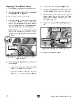
6. Loosen bevel lock knobs (see Figure 27).
7. Starting on end that is not perpendicular,
loosen jam nut (see
Figure 27) on bevel limit
stop bolt.
8. While holding machinist's square against
blade, adjust bevel limit stop bolt (see
Figure 27) until table and blade are perpen-
dicular, then tighten jam nut.
9. Reposition scale pointer (see Figure 27) to
0°.
10. Re-install clear blade guard.
Figure 27. Adjusting bevel limit stop to 0°.
5. Move carriage to opposite end of table, and
repeat
Step 4.
— If table and blade are perpendicular at
both ends of table, no adjustment is
needed.
— If table and blade are not perpendicular at
one or both ends of the table, proceed to
Step 6.
4. With saw against 0˚ bevel stops and bevel
lock knobs tightened, place machinist's
square against table and blade, as shown
in
Figure 26. Blade should be flush with
machinist's square.
Note: If the base of the machinist's square
contacts the abrasive rim, look for a consis-
tent gap along edge where the square meets
the blade.
Figure 26. Machinist's square placed against
table and blade.
Machinist's
Square
Scale
Pointer
Bevel Lock
Knob (1 of 2)
Jam Nut
Bevel Limit
Stop Hex Bolt