-16-
Model T27710 (Mfd. Since 04/16)
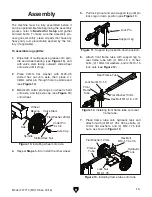
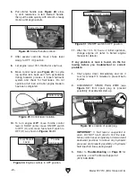
8. Remove cylinder cover, then attach hydraulic
cylinder to splitting wedge with pre-installed
(1) M12-1.75 x 65 hex bolt and (1) M12-1.75
lock nut (see
Figure 14).
Cylinder
Cover
Splitting
Wedge
Hydraulic
Cylinder
Hex Bolt
M12-1.75 x 65
Lock Nut
M12-1.75
Cylinder Cover
Splitting
Wedge
Hydraulic
Cylinder
Hex Bolt
M12-1.75 x 65
Hex Bolt
M10-1.5 x 20
Lock Nut
M12-1.75
Flat Washer 10mm
Lock Washer 10mm
Figure 14. Attaching hydraulic cylinder to
splitting wedge.
Clevis Pin
Hairpin
Cotter Pin
Beam
Frame
Tube
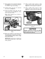
Figure 16. Attaching hydraulic cylinder and
beam to frame tube.
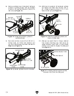
9. Re-install cylinder cover with (8) M10-1.5 x
20 hex bolts, (8) 10mm lock washers, and
(8) 10mm flat washers that were removed in
Step 8 (see Figure 15).
10. With help of assistant, lift hydraulic cylinder
and beam onto frame tube. Secure with (1)
21 x 126mm clevis pin and (1) 1
3
⁄
4
" x 2
1
⁄
2
"
hairpin cotter pin (see
Figure 16).
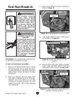
Figure 17. Installing rubber spacers and flat
washers onto motor mounting pad.
Fender Washer 10mm
Rubber Spacer
Mounting Pad
11. Remove any paint chips or foreign material
from engine mounting pad, then place (4)
rubber spacers—each with a 10mm fender
washer—over holes on engine mounting pad
(see
Figure 17).
Cylinder Cover
Hex Bolt
M10-1.5 x 20
Flat Washer
10mm
Lock Washer
10mm
Figure 15. Hydraulic cylinder cover re-installed.
Summary of Contents for T27710
Page 40: ...38 Model T27710 Mfd Since 04 16...
Page 44: ......
Page 45: ......
Page 46: ......
Page 47: ......
Page 48: ......
Page 49: ......
Page 50: ......
Page 51: ......
Page 52: ......
Page 53: ......
Page 54: ......
Page 55: ......
Page 56: ......
Page 57: ......
Page 58: ......
Page 59: ......
Page 60: ......
Page 61: ......
Page 62: ......
Page 115: ...53 18 690 01 Rev C KohlerEngines com...
Page 116: ...54 KohlerEngines com 18 690 01 Rev C...
Page 117: ...55 18 690 01 Rev C KohlerEngines com...
Page 118: ...56 KohlerEngines com 18 690 01 Rev C 2015 by Kohler Co All rights reserved...


