Grizzly G0855 Owner'S Manual Download Page 33

Model G0855/G0856 (Mfd. Since 02/19)

-31-

Edge Jointing

To edge joint on jointer:

1.  Inspect stock to ensure it is safe and suitable 

for  the  operation

  (see  Stock Inspection & 

Requirements section).

2.  Set  infeed  table  height  to  desired  cutting 

depth for each pass.


 CAUTION: To minimize risk of kickback, 

do not exceed a cutting depth of 

1

8

" per pass.

3.  Set fence to 90°.

4.  Start jointer.

5.  Place  workpiece  firmly  against  fence  and 

infeed table.


 CAUTION: To ensure workpiece remains 

stable during cut, concave sides of workpiece 
must face toward table and fence.

6.  Feed  workpiece  completely  across  cutter-

head  while  keeping  it  firmly  against  fence 
and tables during the entire cut.


 CAUTION: Keep hands at least 4" away 

from cutterhead during the entire cut. Instead 
of allowing a hand to pass directly over cut-
terhead,  lift  it  up  and  over  cutterhead,  and 
safely reposition it on the outfeed side to con-
tinue supporting workpiece. Use push blocks 
whenever  practical  to  further  reduce  risk  of 
accidental hand contact with cutterhead.

7.  Repeat Step 6 until the entire edge is flat.


Tip:  When squaring up stock, cut opposite 
edge of workpiece with a table saw instead 
of the jointer—otherwise, both edges of work-
piece will not be parallel with each other.

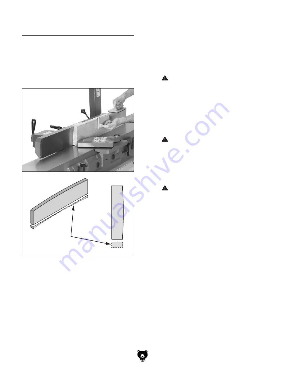
Figure 29. Example photo of an edge jointing 

operation.

Removed

Surface

Edge  jointing  (see  example 

Figures  below)  pro-

duces  a  flat  and  true  surface  along  the  side  of 
a  workpiece  by  removing  uneven  areas.  It  is  an 
essential  step  for  squaring  up  warped  or  rough 
stock and when preparing a workpiece for joinery 
or finishing.

Summary of Contents for G0855

Page 1: ...dels manufactured since 02 19 COPYRIGHT OCTOBER 2018 BY GRIZZLY INDUSTRIAL INC REVISED JANUARY 2019 ES WARNING NO PORTION OF THIS MANUAL MAY BE REPRODUCED IN ANY SHAPE OR FORM WITHOUT THE WRITTEN APPR...

Page 2: ...g grinding tool integrity and the usage of personal protective equipment The manufacturer will not be held liable for injury or property damage from negligence improper training machine modifications...

Page 3: ...ting Replacing Spiral Cutterhead Inserts G0856 45 Adjusting Gibs 46 Checking Adjusting Table Parallelism 47 Setting Outfeed Table Height 48 Setting Fence Stops 49 Calibrating Depth of Cut Scale 51 Ten...

Page 4: ...e mistakes but our policy of continuous improvement also means that sometimes the machine you receive is slightly different than shown in the manual If you find this to be the case and the difference...

Page 5: ...ations c Never make jointing or rabbeting cuts deeper than 1 8 or planing cuts deeper than 1 16 d Always use hold down or push blocks when jointing material narrower than 3 or planing material thinner...

Page 6: ...workpiece after it passes over cutterhead For optimum results outfeed table must be properly adjusted even with highest point of cutterhead knives inserts D Fence Supports workpiece laterally as it mo...

Page 7: ...with 90 stop bolt When engaged stops fence at 90 When disengaged allows bevel cuts greater than 90 Q 45 Inward Fence Stop Stops fence at 45 inward R 90 Stop Fence Stop Stops fence at 90 S 45 Outward F...

Page 8: ...Dimensions Carton 1 Type Wood Crate Content Machine Weight 373 lbs Length x Width x Height 74 x 25 x 15 in Must Ship Upright Yes Carton 2 Type Cardboard Box Content Stand Weight 115 lbs Length x Width...

Page 9: ...pe 4 Knife Cutterhead Diameter 3 1 16 in Cutterhead Speed 5500 RPM Knife Information Number of Knives 4 Knife Type HSS Single Sided Knife Length 8 in Knife Width 3 4 in Knife Thickness 1 8 in Knife Ad...

Page 10: ...g Dimensions Carton 1 Type Wood Crate Content Machine Weight 373 lbs Length x Width x Height 74 x 25 x 15 in Must Ship Upright Yes Carton 2 Type Cardboard Box Content Stand Weight 115 lbs Length x Wid...

Page 11: ...d Diameter 3 1 16 in Number of Cutter Spirals 4 Number of Indexable Cutters 36 Cutterhead Speed 5500 RPM Cutter Insert Information Cutter Insert Type Indexable Carbide Cutter Insert Length 15 mm Cutte...

Page 12: ...d proof DANGEROUS ENVIRONMENTS Do not use machinery in areas that are wet cluttered or have poor lighting Operating machinery in these areas greatly increases the risk of accidents and injury MENTAL A...

Page 13: ...th moving parts or flying debris Make sure they are properly installed undamaged and working correctly BEFORE operating machine FORCING MACHINERY Do not force machine It will do the job safer and bett...

Page 14: ...ease risk of kickback It also requires more cutting force which produces chat ter or excessive chip out Always joint or surface plane WITH the grain CUTTING LIMITATIONS Cutting workpieces that do not...

Page 15: ...ire may result especially if connected to an undersized circuit To reduce the risk of these hazards avoid over loading the machine during operation and make sure it is connected to a power supply circ...

Page 16: ...Any extension cord used with this machine must be in good condition and contain a ground wire and matching plug receptacle Additionally it must meet the following size requirements Minimum Gauge Size...

Page 17: ...solved any issues between Grizzly or the shipping agent You MUST have the original pack aging to file a freight claim It is also extremely helpful if you need to return your machine later Unpacking SU...

Page 18: ...1 Cardboard Box Figure 8 Qty B Stand 1 Loose Items Figure 9 Qty C Switch Pedestal Assembly 1 D Lock Washers 8mm Pedestal 2 E Cap Screws M8 1 25 x 70 Pedestal 2 F Handwheels 2 G Lock Washers 10mm 3 H...

Page 19: ...Model G0855 G0856 Mfd Since 02 19 17 Hardware Recognition Chart USE THIS CHART TO MATCH UP HARDWARE DURING THE INVENTORY AND ASSEMBLY PROCESS 5mm 5mm Flat Head Cap Screw...

Page 20: ...fety glasses disposable gloves Plastic paint scraper optional Basic steps for removing rust preventative 1 Put on safety glasses 2 Coat the rust preventative with a liberal amount of cleaner degreaser...

Page 21: ...ation Physical Environment The physical environment where the machine is operated is important for safe operation and lon gevity of machine components For best results operate this machine in a dry en...

Page 22: ...ry assistance from other people If using power lifting equipment such as a forklift or crane each piece of lifting equipment must be rated for at least 600 lbs to support dynamic loads that may be app...

Page 23: ...re 13 Table assembly secured to stand 9 Loosen motor mount fasteners shown in Figure 15 DO NOT completely remove fasteners 10 Slide motor upward place V belt around cutterhead pulley and motor pulley...

Page 24: ...assembly including belt cover Figure 17 Proper pulley alignment Cutterhead Pulley Motor Pulley Alignment If pulleys are aligned proceed to Step 14 If pulleys are not aligned perform Steps 12 13 12 Lo...

Page 25: ...screw 1 of 2 x 2 21 Verify outfeed table height is set correctly with knives inserts at top dead center TDC refer to Setting Outfeed Table Height on Page 48 and all knives inserts are securely tighten...

Page 26: ...then pull ing cutterhead guard back and letting it go It should spring back over cutterhead and con tact fence without dragging across outfeed table If cutterhead guard does not spring back over cutt...

Page 27: ...24 Example of dust hose attached to dust port Test Run Once assembly is complete test run the machine to ensure it is properly connected to power and safety components are functioning correctly If yo...

Page 28: ...ing a padlock through the ON START button as shown Locking the switch in this manner can prevent unauthorized operation of the machine which is especially important if the machine is not stored insid...

Page 29: ...are not experienced with this type of machine WE STRONGLY RECOMMEND that you seek additional training outside of this manual Read books magazines or get formal training before beginning any proj ects...

Page 30: ...make additional passes Only cut natural wood This jointer is only designed for cutting natural wood stock Never use it to cut MDF particle board ply wood laminates drywall backer board metals glass s...

Page 31: ...sly Jointed Edge 4 Rip Cut on a Table Saw Jointed edge of workpiece is placed against a table saw fence and opposite edge cut off Squaring stock means making it flat and paral lel along both length an...

Page 32: ...ks whenever practical to further reduce risk of accidental hand contact with cutterhead 3 Set fence to 90 4 Start jointer 5 Place workpiece firmly against fence and infeed table CAUTION To ensure work...

Page 33: ...p hands at least 4 away from cutterhead during the entire cut Instead of allowing a hand to pass directly over cut terhead lift it up and over cutterhead and safely reposition it on the outfeed side t...

Page 34: ...iece over cutter head with a push block in your trailing hand CAUTION When your leading hand gets within 4 of the cutterhead lift it up and over cutterhead and place push block on portion of the workp...

Page 35: ...ot be safe or appropriate for making the rabbet cut on this jointer In these cases you need to use another tool or method for rabbet cutting that will be a safer alternative A rabbet cut can alternati...

Page 36: ...ut per pass when surface planing on this machine or kickback and serious injury may occur Figure 32 Infeed table height controls Infeed Table Lock Infeed Table Handwheel 4 Set fence to 90 and near fro...

Page 37: ...tory set and cannot be adjusted Item s Needed Qty Wrench 13mm 1 Hex Wrench 4mm 1 Infeed Positive Stops Positive Stop Screws To lower the infeed table below the 1 8 depth stop pull the release knob see...

Page 38: ...ose 4 x 10 W1034 Heavy Duty Clear Flex Hose 4 x 10 D2107 Hose Hanger 41 4 W1015 Y Fitting 4 x 4 x 4 W1017 90 Elbow 4 W1019 Hose Coupler Splice 4 W1317 Wire Hose Clamp 4 W1007 Plastic Blast Gate 4 W105...

Page 39: ...setting system lets you set jointer knives in perfect alignment every time Figure 40 W1211A Jointer Pal Knife Gauge H4982 HSS Jointer Knives 4 Pk 8 x 3 4 x 1 8 replacement HSS jointer knives Figure 39...

Page 40: ...achine is simple Vacuum excess wood chips and sawdust and wipe off the remaining dust with a dry cloth If any resin has built up use a resin dissolving cleaner to remove it Treat all unpainted cast ir...

Page 41: ...ed and permanently lubricated simply leave them alone until they need to be replaced DO NOT lubricate them It is essential to clean components before lubri cating them because dust and chips build up...

Page 42: ...ollection blockage 7 Motor overheated 8 Pulley slipping on shaft 9 Run capacitor at fault 10 Centrifugal switch at fault 11 Motor bearings at fault 12 Motor at fault 1 Ensure workpiece is suitable for...

Page 43: ...tent is less than 20 Allow to dry if necessary 2 Sharpen replace knives Page 43 rotate replace inserts Page 45 Long lines or ridges that run along length of workpiece 1 Nicked or chipped knives insert...

Page 44: ...traightedge or Jointer Pal is held flat against the outfeed table and the knife heights are set to the bottom of the straightedge as shown Because the knife projection height from the cutterhead is de...

Page 45: ...cutterhead both legs of jig sit firmly on cutterhead body and middle pad of jig just touches top edge of knife If jig does not sit as described then that knife must be reset Repeat this inspec tion wi...

Page 46: ...ly touch middle pad of knife jig or bottom of straightedge in each of the straightedge positions Snug gib bolts just tight enough to hold knife in place Repeat with remaining knives 8 Rotate cutterhea...

Page 47: ...arp unused and which edges are dull or dam aged Replace inserts once the reference dot has been rotated back to its original position Reference Dot Figure Insert rotating sequence Figure 57 Insert rot...

Page 48: ...wipe excess off and torque screw to 48 50 inch pounds IMPORTANT If too much oil is applied to the threads excess will attempt to squeeze out of threaded hole as you install insert and force it to rai...

Page 49: ...xtend straightedge over both tables raise infeed table until it contacts straight edge see Figure 60 then lock infeed table 5 Look down length of straightedge on outfeed side to see if there are any n...

Page 50: ...5 G0856 Figure 63 Location of outfeed table lock Outfeed Table Lock Setting Outfeed Table Height To help ensure safe operation and best cutting results set the outfeed table height level with the kniv...

Page 51: ...st fence and table as shown in Figure 69 Figure 69 Example of adjusting fence to 90 Setting Fence Stops 3 Place sliding bevel set to 45 against fence and table as shown in Figure 67 1 DISCONNECT MACHI...

Page 52: ...sting fence 45 outward 3 Place sliding bevel set to 135 against fence and table as shown in Figure 71 Setting 45 Outward 135 Stop 4 Loosen jam nut on 45 stop bolt and adjust stop bolt until fence is e...

Page 53: ...scale 1 DISCONNECT MACHINE FROM POWER 2 Make sure outfeed table height is set cor rectly refer to Setting Outfeed Table Height on Page 48 3 Move cutterhead guard out of the way and slide fence all the...

Page 54: ...of motor mount fasteners 3 of 4 shown Figure 75 Checking belt tension Motor Pulley Approximately 1 4 Deflection Cutterhead Pulley If there is more than 1 4 deflection when you check belt tension repea...

Page 55: ...o check pulley alignment see Figures 76 77 If available use a narrow straightedge against pulley faces to check alignment Checking Aligning Pulleys Checking Aligning Pulleys Figure 77 Proper pulley al...

Page 56: ...en pull cutterhead guard see Figure 78 back and let it go If cutterhead guard springs back over cutterhead contacts fence and does not drag across outfeed table then it is prop erly adjusted If cutter...

Page 57: ...rent at the time of printing but may not match your machine If you find this to be the case use the wiring diagram inside the motor junction box CAPACITORS INVERTERS Some capacitors and power inverter...

Page 58: ...4 Hot Hot Ground 6 20 Plug 230 VAC G Ground WARNING SHOCK HAZARD Disconnect power before working on wiring Run Capacitor 70uF 250VAC Start Capacitor 400uF 125VAC ON STOP Switch KJD17B 230V Paddle Swit...

Page 59: ...34 30 40 40 3 39 35 35 40 3 40 40 4 40 5 40 2 36 36 40 6 68 68 68 42 41 31 42 41 31 31 1 2 3 4 5 6 7 8 9 5 23 28 27 65 17 26 25 29 63 8 9 10 19 18 20 21 22 24 23 11 12 13 14 15 16 111 117 130 131 132...

Page 60: ...103 99 92 102 104 110 101 109 106 100 108 105 107 54 98 93 60 61 62 64 31 66 59 67 72 71 70 59 46 43 44 58 14 112 113 114 115 116 118 52 53 51 50 47 48 57 56 55 49 48 47 14 83 69 71 86 86 3 86 4 86 5...

Page 61: ...76 P0855076 DUST PORT 4 28 P0855028 CAP SCREW 1 4 20 X 1 2 77 P0855077 PHLP HD SCR 1 4 20 X 1 2 29 P0855029 FLAT WASHER 1 4 78 P0855078 LOCK WASHER 10MM 30 P0855030 FENCE BASE 79 P0855079 STANDOFF HE...

Page 62: ...LOCK WASHER 1 2 123 P0855123 TAP SCREW M6 X 8 100 P0855100 KEY 5 X 5 X 22 124 P0855124 ADJUSTABLE FOOT M8 1 25 101 P0855101 HEX NUT 5 16 18 125 P0855125 HEX NUT M8 1 25 102 P0855102 TABLE BASE 126 P0...

Page 63: ...Taiwan Date S N MODEL G0855 8 DOVETAIL JOINTER w MOBILE BASE 175370 201 203 203 204 205 207 208 206 202 210 211 212 206 209 214 213 G0856 To reduce the risk of serious injury when using this machine...

Page 64: ......

Page 65: ...metalworker ____ 0 2 Years ____ 2 8 Years ____ 8 20 Years ____20 Years 6 How many of your machines or tools are Grizzly ____ 0 2 ____ 3 5 ____ 6 9 ____10 7 Do you think your machine represents a good...

Page 66: ...LINE FOLD ALONG DOTTED LINE GRIZZLY INDUSTRIAL INC P O BOX 2069 BELLINGHAM WA 98227 2069 Place Stamp Here Name_______________________________ Street_______________________________ City______________S...

Page 67: ...shall be tried in the State of Washington County of Whatcom We shall in no event be liable for death injuries to persons or property or for incidental contingent special or consequential damages arisi...

Page 68: ......

Reviews: