


-40-
G0783 (Mfd. Since 05/15)
91
92
94
95
96
97
98
99
100
101
102
103
104
105
145
107
108
109
110
111
112
113
114
115
116
117
118
119
120
122
117
124
125
146
79
80
87
86
147
149
148
150
151
109
109
107
93
152
153
153
152
106
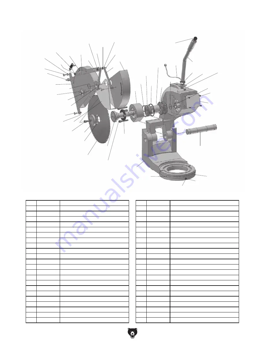
Column & Headstock
REF PART #
DESCRIPTION
REF PART #
DESCRIPTION
79
P0783079
PIVOT SHAFT
110
P0783110
UPPER BLADE HOOD
80
P0783080
MITER SCALE
111
P0783111
BEARING HOUSING
86
P0783086
CAP SCREW M3-.5 X 6
112
P0783112
EXT RETAINING RING 72MM
87
P0783087
IDENTIFICATION PLATE
113
P0783113
BALL BEARING 6207-OPEN
91
P0783091
OIL SEAL 45 X 65 X 14
114
P0783114
O-RING 75 X 2.7
92
P0783092
BLADE SPINDLE
115
P0783115
SPACER
93
P0783093
SAW BLADE 11" X 180-TOOTH
116
P0783116
WORM GEAR
94
P0783094
ROLL PIN 8 X 20
117
P0783117
EXT RETAINING RING 32MM
95
P0783095
BLADE FLANGE
118
P0783118
NEEDLE BEARING BK3026
96
P0783096
CAP SCREW M10-1.5 X 25 LH
119
P0783119
LEVER ARM CABLE 36" RUBBER
97
P0783097
LOWER BLADE HOOD
120
P0783120
LEVER ARM M22-2.5
98
P0783098
CLEVIS PIN 8 X 18 GROOVED
122
P0783122
POWER BUTTON ONPOW LAS1-A 5A
99
P0783099
BLADE HOOD LINKAGE 9-1/2"
124
P0783124
CLEVIS PIN 8 X 13 GROOVED
100
P0783100
HOOD ROD PIVOT
125
P0783125
SPACER 2 X 30MM (NYLON)
101
P0783101
CAP SCREW M10-1.5 X 60
145
P0783145
HOOD ROD PIVOT
102
P0783102
COOLANT SHUT-OFF VALVE
146
P0783146
HOOD PIVOT SPACER
103
P0783103
EXT RETAINING RING 9MM
147
P0783147
BASE
104
P0783104
BLADE HOOD LINKAGE 11-1/2"
148
P0783148
SPACER 8 X 2MM (NYLON)
105
P0783105
CLEVIS PIN 8 X 15 GROOVED
149
P0783149
CLEVIS PIN 8 X 22 GROOVED
106
P0783106
BLADE HOOD LINKAGE 7-1/2"
150
P0783150
FLAT WASHER 22MM
107
P0783107
SPACER 8 X 3MM (NYLON)
151
P0783151
HEX NUT M22-2.5
108
P0783108
BLADE HOOD LINKAGE 6-1/2"
152
P0783152
LEVER ARM POINTER
109
P0783109
EXT RETAINING RING 8MM
153
P0783153
RIVET 2 X 6MM NAMEPLATE, STEEL
Summary of Contents for G0783
Page 48: ......