background image

-90-

Model G0764Z (Mfd. Since 10/15)

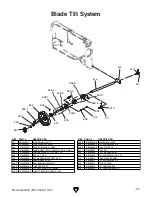
1

77

78

2

3

4

8 9

12

13

12

13

14

16

16-1

17

18

19

20

20-1

20-2

24

27

28

29

30

31

32

33

34

31

32

33

34

35

36

37

38

39

5

11

6

6

10

7

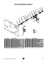
40

41

42

43

44 45

46

47

48

49

50

51

55

56

57

58

59

60

61

62

63

64

65 66 67

68 69

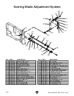
71

71-1

71-2

71-3
71-4

71-5

71-5

71-6

71-7

71-8

71-9

71-10

71-11

71-12

71-13

71-14

72

73

74

75

80

81

76

99

82

83

84

86

87

88

89

89

89

90

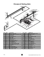
52

79

53

54

21

22

23

91

92

93

95

96

97

Body

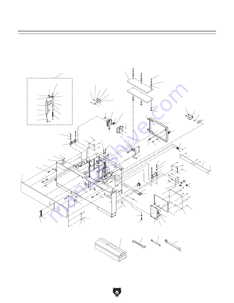
SECTION 9: PARTS

We do our best to stock replacement parts when possible, but we cannot guarantee that all parts shown 
are available for purchase. Call 

(800) 523-4777 or visit www.grizzly.com/parts to check for availability.

Summary of Contents for G0764Z

Page 1: ...ls manufactured since 10 16 COPYRIGHT AUGUST 2016 BY GRIZZLY INDUSTRIAL INC REVISED MAY 2017 JH WARNING NO PORTION OF THIS MANUAL MAY BE REPRODUCED IN ANY SHAPE OR FORM WITHOUT THE WRITTEN APPROVAL OF GRIZZLY INDUSTRIAL INC MN17972 PRINTED IN TAIWAN V2 05 17 ...

Page 2: ...ng grinding tool integrity and the usage of personal protective equipment The manufacturer will not be held liable for injury or property damage from negligence improper training machine modifications or misuse Some dust created by power sanding sawing grinding drilling and other construction activities contains chemicals known to the State of California to cause cancer birth defects or other repr...

Page 3: ...p Cutting 57 Crosscutting 59 Miter Cutting 61 Dado Cutting 62 Rabbet Cutting 63 Narrow Rip Auxiliary Fence Push Block 64 SECTION 5 ACCESSORIES 66 SECTION 6 MAINTENANCE 68 Schedule 68 Cleaning Protecting 68 Lubrication 69 SECTION 7 SERVICE 70 Troubleshooting 70 Belt Service 72 Blade Tilt Calibration 74 Sliding Table Parallel Adjustment 75 Sliding Table Movement Adjustment 76 Squaring Crosscut Fence...

Page 4: ...s or need help contact us with the information below Before contacting make sure you get the serial number and manufacture date from the machine ID label This will help us help you faster Grizzly Technical Support 1815 W Battlefield Springfield MO 65807 Phone 570 546 9663 Email techsupport grizzly com We want your feedback on this manual What did you like about it Where could it be improved Please...

Page 5: ...ts dust from the cutting operation Refer to Figures 1 5 and the following descriptions to become familiar with the basic controls and compo nents of this machine Understanding these items and how they work will help you understand the rest of the manual and stay safe when operating this saw F Rip Fence Fully adjustable with micro adjustment knob for precision cuts of smaller workpieces Fence face ...

Page 6: ...e rip fence assembly into position along the fence rail so that the workpiece is stable when cut ting Q Micro Adjust Lock Knob Enables the use of the micro adjust knob for precise position ing of the rip fence Saw Blades L Rip Fence Scale Helps you measure the cut when rip cutting M Slide Lock Handle Secures the aluminum fence face on its forward backward slide track to support the workpiece N Mic...

Page 7: ...provides a visual indicator that power is enabled to the saw AC Emergency Stop Button Turns both motors OFF Twist clockwise until it pops out to reset AD Master Power Switch Enables power flow to the machine AE Scoring Blade Elevation Knob Raises and lowers the scoring blade to change the kerf thickness The knurled wheel behind the knob secures the setting to prevent blade from moving during opera...

Page 8: ...d the operator with what sounds like a horrible explosion The danger comes from flying stock striking the operator or bystanders The operator s hands may also be pulled into the blade during the kickback Refer to Preventing Kickback on Page 14 for addi tional information Parallel When two objects are spaced an equal distance apart at every point along two given lines or planes I e the rip fence fa...

Page 9: ...0 523 4777 Fax 800 438 5901 SLIDING TABLE SAW CAPACITIES Ripping Width Miter Cut 90º push cut Miter Cut 45º Miter Cut 45º push cut Cross Cut fence not extended Miter Cut 45º push cut fence not extended Miter Cut 45º fence not extended Cross Cut 511 4 134 124 731 4 126 731 4 124 134 58 731 4 58 134 126 90 134 42 ...

Page 10: ...t 1397 lbs Length x Width x Height 83 x 45 x 44 in Must Ship Upright Yes Carton 2 Type Wood Crate Content Sliding Table Weight 246 lbs Length x Width x Height 130 x 17 x 9 in Must Ship Upright Yes Electrical Power Requirement 220V or 440V 3 Phase 60 Hz Prewired Voltage 220V Full Load Current Rating 29 2A at 220V 14 6A at 440V Minimum Circuit Size 40A at 220V 20A at 440V Connection Type Permanent H...

Page 11: ...tion Floor To Table Height 34 1 2 in Table Size Length 39 1 2 in Table Size Width 21 1 2 in Table Size Thickness 2 5 16 in Table Size With Ext Wings Length 35 1 4 in Table Size With Ext Wings Width 59 1 8 in Table Size With Ext Wings Thickness 2 1 2 in Sliding Table Length 126 in Sliding Table Width 14 in Sliding Table Thickness 6 3 4 in Sliding Table T Slot Top Width 5 8 in Sliding Table T Slot H...

Page 12: ...ear Approximate Assembly Setup Time 3 Hours Serial Number Location ID Label on Side of Machine ISO 9001 Factory Yes Certified by a Nationally Recognized Testing Laboratory NRTL No Features Micro Adjustable Rip Fence Scoring Saw Blade for Tear Out Free Cutting Sliding Table on Steel Ball Guide System with Heat Treated Steel Ways Alloy Crosscut Fence for Miter Cutting 45 Deg Right and Left Miter Fen...

Page 13: ... proof DANGEROUS ENVIRONMENTS Do not use machinery in areas that are wet cluttered or have poor lighting Operating machinery in these areas greatly increases the risk of accidents and injury MENTAL ALERTNESS REQUIRED Full mental alertness is required for safe operation of machin ery Never operate under the influence of drugs or alcohol when tired or when distracted For Your Own Safety Read Instruc...

Page 14: ...h moving parts or flying debris Make sure they are properly installed undamaged and working correctly BEFORE operating machine FORCING MACHINERY Do not force machine It will do the job safer and better at the rate for which it was designed NEVER STAND ON MACHINE Serious injury may occur if machine is tipped or if the cutting tool is unintentionally contacted STABLE MACHINE Unexpected movement dur ...

Page 15: ...tting operation Never start saw with workpiece touching blade Allow blade to reach full speed before cutting Only feed workpiece against direc tion of main blade rotation Always use some type of guide to feed workpiece in a straight line Never back workpiece out of cut or move it backwards or sideways after starting a cut Feed cuts all the way through to completion Never perform any operation free...

Page 16: ...Ensure rip fence is adjusted parallel with the blade otherwise the chances of kickback are extreme Take the time to check and adjust the rip fence before cutting Preventing Kickback Even if you know how to prevent kickback it may still happen Here are some precautions to help protect yourself if kickback DOES occur Stand to the side of the blade path when cutting If a kickback does occur the throw...

Page 17: ...er loading the machine during operation and make sure it is connected to a power supply circuit that meets the specified circuit requirements Circuit Requirements for 220V This machine is prewired to operate on a power supply circuit that has a verified ground and meets the following requirements Nominal Voltage 220V 230V 240V Cycle 60 Hz Phase 3 Phase Power Supply Circuit 40 Amps Circuit Requirem...

Page 18: ... system having an equipment grounding conductor All grounds must be verified and rated for the electrical requirements of the machine Improper grounding can increase the risk of electric shock The Model G0764Z can be converted for 440V operation This conversion job consists of 1 Disconnecting the saw from the power source 2 moving the fuse to the 440V holder 3 replacing the overload relays and 4 r...

Page 19: ... W1 W2 U2 V2 E U1 FOTEK H3 TRD 30S Figure 8 Moving fuse to 440V fuse holder 4 Replace left overload relay with TH P12 overload relay and set amperage dial to 1 7A see Figure 9 1L1 5L3 13NO 3L2 2T1 6T3 4T2 14NO A2 A1 A2 A1 S P11 KS Shihlin 1L1 5L3 13NO 3L2 21NC 2T1 6T3 4T2 22NC 14NO Shihlin S P21 KM A2 A1 1L1 5L3 13NO 3L2 21NC 2T1 6T3 4T2 22NC 14NO Shihlin S P21 KY A2 A1 1L1 5L3 13NO 3L2 21NC 2T1 6...

Page 20: ...safety glasses during the entire setup process HEAVY LIFT Straining or crushing injury may occur from improperly lifting machine or some of its parts To reduce this risk get help from other people and use a forklift or other lifting equipment rated for weight of this machine This machine was carefully packaged for safe transport When unpacking separate all enclosed items from packaging materials a...

Page 21: ...Model G0764Z Mfd Since 10 15 19 5mm Hardware Recognition Chart ...

Page 22: ...ust Hose 1 Inventory Inventory Figure 10 Qty A Small Extension Table 1 Set Screws M10 1 5 x 20 2 Hex Nuts M10 1 5 2 B Large Extension Table 1 Set Screws M10 1 5 x 20 3 Hex Nuts M10 1 5 3 C Crosscut Table 1 D Crosscut Fence 1 E Crosscut Table Brace 1 F Rip Fence Rail w Fasteners 1 G Rip Fence Scale 1 H Rip Fence 1 I Cabinet Door 1 These are the loose components shipped with the machine Before setup...

Page 23: ...wn Qty Combo Wrenches 30mm Toolbox 2 Open End Wrench 19 22mm Toolbox 1 Open End Wrench 36mm Toolbox 1 Lock Washers 12mm Sliding Table 3 Flat Washers 12mm Sliding Table 3 Hex Nuts M12 1 75 Sliding Table 3 B H Cap Screws M6 1 x 12 Fence Scale 3 Flat Washers 6mm Rip Fence Scale 4 Hex Nut M6 1 Rip Fence Scale 2 Cap Screw M8 1 25 x 15 Fence Rail 1 Lock Washer 8mm Fence Rail 1 Flat Washer 12mm Crosscut ...

Page 24: ...ic paint scraper optional Basic steps for removing rust preventative 1 Put on safety glasses 2 Coat the rust preventative with a liberal amount of cleaner degreaser then let it soak for 5 10 minutes 3 Wipe off the surfaces If your cleaner degreas er is effective the rust preventative will wipe off easily If you have a plastic paint scraper scrape off as much as you can first then wipe off the rest...

Page 25: ...Environment The physical environment where the machine is operated is important for safe operation and lon gevity of machine components For best results operate this machine in a dry environment that is free from excessive moisture hazardous chemi cals airborne abrasives or extreme conditions Extreme conditions for this type of machinery are generally those where the ambient temperature range exce...

Page 26: ...e Position forklift forks as wide as they can be while still fitting under center opening see Figure 15 Figure 15 How to insert forks for lifting table saw off pallet DO NOT lift saw any higher than necessary to clear pallet Serious personal injury and machine damage may occur if safe moving methods are not followed 4 With an assistant holding each end to help stabilize load lift saw with forklift...

Page 27: ...d make the required adjustments to prepare the saw for the test run To assemble sliding table saw 1 Turn sliding table upside down as shown in Figure 16 2 Insert 3 M12 1 75 x 50 T bolts into T slot along bottom of sliding table see Figure 17 and space them the same distance apart as mounting holes in cabinet frame 3 Lift sliding table over saw and lower T bolts into mounting holes on frame as show...

Page 28: ...e Figure 19 Slide table control end handle End Plate w Handle 6 Remove access covers on each side of the frame to reach the T bolts on the ends of the sliding table Figures 21 22 Reach through cabinet access hole to reach middle sliding table T bolt Figure 23 Figure 21 Sliding table T bolt access on rear side at back of saw Sliding Table T Bolt 5 Position sliding table against parallelism adjustme...

Page 29: ...tension table attached to cabinet 12 Place a straightedge across cast iron table and large extension table to see if tables are parallel If entire length of straight edge is parallel with both tables move on to Step 14 If both tables are not parallel with straight edge loosen hex nuts on set screws shown in Figure 28 Adjust set screws to align top of extension table with top of cast iron table the...

Page 30: ...x nuts used to level extension table Figure 31 Rip fence scale attached flush with top edge of cast iron table and large extension table Rip Fence Scale x 1 x 2 18 The rip fence rail is pre assembled with four rail studs and accompanying hardware Remove 1 hex nut 1 flat washer and 1 lock washer from end of each stud as shown in Figure 32 Rail Studs Figure 32 Removing rip fence rail hardware to pre...

Page 31: ...k it with slide lock handle Figure 35 Rip fence attached to rip fence base Rip Fence Clamping Plate Slide Lock Handle Figure 34 Rip fence attached with lock handles and lock knob installed Lock Handles Fence Base Knob Bolt 23 Move sliding table all the way forward to expose blade cover Pull blade cover toward front of machine to disengage magnetic catches see Figure 36 Figure 36 Location of magnet...

Page 32: ... 40 Figure 40 Main blade installed on arbor Before proceeding with the next steps wear gloves to protect your hands when handling and installing the blade 27 Slide main blade not included over arbor with teeth facing to the right then install flange see Figure 39 Figure 39 Main blade component assembly Arbor Flange Arbor Nut Upper Teeth Facing Right 26 Continue unthreading arbor nut clockwise it h...

Page 33: ...e Figure 41 Rip fence stop ring attached to rail Rip Fence Stop Ring w Set Screw 33 Install rip fence end stop on opposite end of rip fence rail with 1 M8 1 25 x 15 cap screw and 1 8mm lock washer see Figure 42 Figure 42 Rip fence end stop attached to rail Rip Fence End Stop 34 Adjust rip fence to main blade and tables as instructed in Calibrating Rip Fence on Page 79 35 Thread M12 1 75 x 55 adjus...

Page 34: ...Figure 45 39 Turn crosscut fence onto its side 40 On crosscut fence end nearest blade a Insert 1 M8 1 25 T nut into T slot then loosely thread M8 1 25 pivot bolt with 8mm fiber flat washer into T nut see Figure 46 b Position crosscut fence so edge cap see Figure 46 is close to but not touching main blade c Align the pivot bolt with pivot hole see Figure 46 then fully tighten pivot bolt Note Long k...

Page 35: ...t Plate T Bolt Figure 49 Flip stop attached to crosscut fence Flip Stop T Nut 43 Without moving previously installed hard ware flip crosscut fence over and insert pivot bolt and T slot bolt into appropriate hole slot 44 Secure crosscut fence to crosscut table by a From underneath left side of crosscut fence threading M8 1 25 long knob with 8mm fender washer onto pivot bolt b From underneath middle...

Page 36: ... until arm support base is parallel with floor see Figure 53 on Page 35 Tip Check this position by using a tape to measure the distance between each end of the arm support base and the floor Note This parallel position helps ensure the blade guard is parallel with the table once it is installed For now this positioning should be very close It will be checked and if neces sary fine tuned in a later...

Page 37: ...ing arm support pedestal Arm Support Pedestal x 4 Bracket Arm Leveling Bolt M20 2 5 Hex Nut w Fender Washer 1 of 2 Jam Nut 54 Insert upper support arm through top of arm support pedestal as shown in Figure 55 55 Install 1 M10 1 5 x 30 hex bolt into location shown in Figure 55 Do not tighten yet Upper Support Arm x 1 Figure 55 Installing upper support arm Top of Arm Support Pedestal 56 Install dust...

Page 38: ...heck to make sure both blade rollers are centered over blade and if necessary loosen hex bolt from Step 55 on Page 35 slide upper support arm until rollers are centered over blade then re tighten hex bolt to secure Figure 60 Adjusting alignment of arm support pedestal Cap Screws that Secure Arm Support Pedestal Arm Support Pedestal 58 Attach connection plate assembly to end of upper support arm us...

Page 39: ...nob shown in Figure 63 slide the insert out and replace it with the appropriate insert then re install the lock knob to secure the insert Figure 63 Removing blade guard insert Lock Knob Flat Insert 61 Make sure rollers are parallel with table If necessary loosen M20 2 5 hex nuts from Step 52 repeat Steps 50 51 until rollers are parallel with table then re tighten hex nuts 62 Install dust port on u...

Page 40: ... number of branches or wyes and 4 amount of other open lines throughout the system Explaining how to cal culate these variables is beyond the scope of this manual Consult an expert or purchase a good dust collection how to book This machine creates a lot of wood chips dust during operation Breathing airborne dust on a regular basis can result in perma nent respiratory illness Reduce your risk by w...

Page 41: ...lustrated below The machine is now disconnected from the power source Note Lock the switch in the OFF position to restrict others from starting the machine Electrocution fire shock or equipment damage may occur if machine is not properly grounded and connected to power supply Note About Phase Converters Due to the start up load from this machine we do not recommend using a static phase converter t...

Page 42: ...e sure wires have enough slack so they are not pulled tight or stretched 5 Re install junction box cover and perform Test Run in following section to check phase polarity Ground Terminal Make sure incoming ground wire is con nected to right most terminal post in the power junction box so machine is properly grounded An ungrounded or improperly grounded machine may have an electrified frame which c...

Page 43: ...ing the following 1 The motors power up and run correctly 2 the safety features of the Emergency Stop buttons work correctly and 3 the main blade turns for ward clockwise when viewed from front of saw and the scoring blade turns opposite main blade 5 Verify saw is operating correctly by pushing Main Blade and Scoring Blade ON buttons refer to Figure 4 on Page 5 When operating correctly machine run...

Page 44: ... them Do not swap R or T wires with ground wire inside power supply junction box Doing so will electrify machine frame which could cause electrocution Make sure incoming ground wire is only connected to right most terminal post in the power supply junction box so machine is properly grounded 7 Press Emergency Stop button on front of machine to turn machine OFF 8 WITHOUT resetting Emergency Stop bu...

Page 45: ...height 6 Checks outfeed side of machine for proper support and to make sure the workpiece can safely pass all the way through the blade without interference 7 Puts on safety glasses and a respirator Locates push sticks if needed 8 Feeds the workpiece all the way through blade while maintaining firm pressure on workpiece against table and fence 9 Turns machine OFF immediately after cut is complete ...

Page 46: ...through them Wet or Green Stock Cutting wood with a moisture content over 20 causes unneces sary wear on the blades increases the risk of kickback and yields poor results Excessive Warping Workpieces with exces sive cupping bowing or twisting are danger ous to cut because they are unstable and may move unpredictably when being cut Minor Warping Slightly cupped workpieces can be safely supported wi...

Page 47: ...properly maintains blade after the workpiece exits Lock Handle Guard Loosen the hex bolt securing the guard arm see Figure 74 and adjust the guard so the distance between the blade and both side covers is equal For stock up to 1 thick loosen the 4 lock nuts securing guard to guard arm see inset image in Figure 74 1 4 turn each so the blade guard moves smoothly up and down with the workpiece For st...

Page 48: ... must be posi tioned within 3 8mm of the blade as shown in Figure 79 The riving knife see Figure 76 is a metal plate that prevents freshly cut pieces of workpiece from pinching the backside of the blade and causing kickback It also acts as a barrier behind the blade to shield hands from being pulled into the blade if a kickback occurs while the operator is reaching behind the blade Reaching behind...

Page 49: ...lel with the blade refer to Riving Knife Mounting Block on Page 78 The riving knife included with this machine is 0 10 2 5mm thick and is only designed for 14 diam eter blades When choosing a main blade make sure the blade size meets the requirements listed below The thickness of the blade body and teeth can be measured with calipers or any precision measur ing device Blade Size Requirements Body ...

Page 50: ... alternate top bevel and raker tooth profile Teeth are arranged in groups Gullets are small and shallow similar to a cross cut blade then large and deep similar to a ripping blade Alternate Top Bevel and Flat Figure 85 Laminate blade Laminate blade features Best for cutting plywood or veneer 100 120 teeth Triple chip tooth profile Very shallow gullet Triple Chip Blade Thin Kerf Blade A blade with ...

Page 51: ...igure 86 Arbor Pulley Motor Pulley 3000 4000 5000 Figure 87 Belt positions for each speed Figure 86 Location of main motor adjustment lever 3 Rotate motor adjustment lever counterclock wise to release belt tension 4 Inspect the belt If there is any evidence of damage or excessive wear replace it 5 Position belt on correct arbor and motor pul ley set for desired speed refer to Figure 87 for pulley ...

Page 52: ...ge and blade see Figure 90 9 Slide replacement blade over arbor with teeth facing to the right then replace flange Figure 88 Main blade cover in closed position Main Blade Cover Figure 90 Main saw blade and arbor parts Flange Arbor Nut Wrench Arbor Locking Pin Figure 89 Loosening the main blade arbor nut Arbor Nut Main Arbor Locking Hole The Model G0764Z does not ship with a 14 main blade Refer to...

Page 53: ...his prevents workpiece tearout The scoring blade included with the Model G0764Z has wedge shaped teeth that narrow at the top as shown in Figure 92 With this style of scoring blade the kerf thickness is adjusted by changing the height of the scoring blade Raising the scor ing blade higher increases the kerf thickness Scoring Blade Tooth Figure 92 Scoring blade tooth that narrows at the top Replaci...

Page 54: ...for order of assembly 10 Adjust scoring blade to main blade as instructed in the next subsection Figure 95 Scoring blade order of assembly Figure 93 Inserting arbor wrench behind scoring blade to prevent blade from spinning Arbor Wrench Scoring Blade Hex Bolt 7 Use 19mm wrench to unthread arbor hex bolt counterclockwise left hand threads and remove arbor hex bolt flange and blade see Figure 94 Fig...

Page 55: ...rizontal Adjustment Knob Height Adjustment Knob Lock Collar 5 Align scoring blade kerf to main blade kerf by a Positioning straightedge on one side of main blade flat on table and against main blade and scoring blade teeth b Rotating knurled lock collar behind height adjustment knob see Figure 96 on pre vious page counterclockwise to loosen it c Using height adjustment knob to adjust scoring blade...

Page 56: ...on will provide the safest operation The support bar is adjusted accordingly for maximum workpiece support Front Position Crosscut Table Support Bar Rear Position Crosscut Table Support Bar Figure 97 Crosscut fence front and rear table mounting positions Whenever the crosscut fence is moved between the front and rear positions you must verify the fence is square to the blade and the 0 stop bolts a...

Page 57: ...ort Bar 3 Lift fence up and loosen pivot bolt see Figure 100 Figure 100 Crosscut fence pivot bolt and nut Front Hole Rear Hole Angle Scale Bolt Pivot Bolt Nut 4 Re insert pivot bolt into front hole or rear hole and re insert angle scale bolt into angle scale slot 5 Rotate fence so stop block is against 0 stop bolt see Figure 101 Figure 101 Stop block against 0 stop bolt 0 Stop Bolt Block Adjusting...

Page 58: ...osscut table along sliding table 1 DISCONNECT MACHINE FROM POWER 2 Use sliding table lock lever see Figure 105 to secure table in position 3 Loosen crosscut table lock lever shown in Figure 106 4 Position crosscut table along sliding table T slot to desired position then retighten lock lever to secure table Figure 105 Location of sliding table lock lever Sliding Table Lock Lever Figure 106 Locatio...

Page 59: ...rip cutting smaller boards using the machine as a traditional table saw see Figure 108 Smaller lighter boards are easier to slide across the stationary cast iron table surface to the right of the saw blade Rip Fence Workpiece Figure 108 Traditional rip cut with rip fence The edge shoe see Figure 107 is used to stabilize the front end of a workpiece when otherwise unsecured 2 Check to make sure fen...

Page 60: ...sliding table lock lever Sliding Table Lock Lever 2 Lock sliding table in place with table lock lever see Figure 111 5 Position leading edge of rip fence so it extends across extension wing as shown in Figure 114 then retighten lock lever Figure 114 Proper position of rip fence Rip Fence Rip Fence Lock Lever 6 Lift rip fence lock lever see Figure 114 and adjust fence to approximate width of cut 7 ...

Page 61: ... crosscutting full size panels then skip ahead to Crosscutting Full Size Panels If you will be crosscutting smaller panels then skip ahead to Crosscutting Smaller Panels If you will be crosscutting workpieces using the rip fence as a cut off gauge then skip ahead to Crosscutting Using Rip Fence as Cut Off Gauge To understand how to move the crosscut table read Positioning Crosscut Table Along Slid...

Page 62: ...efer to Page 55 for further details 4 Set either flip stop to the desired width of cut Note Extend the crosscut fence slide if the workpiece is more than 73 5 Load workpiece onto table saw in forward mounting location shown in Figure 115 6 Take all necessary safety precautions then perform cutting operation Front Mounting Location Crosscutting Using Rip Fence as Cut Off Gauge 1 Install crosscut fe...

Page 63: ...n Figure 120 to position table for desired angle of cut see Figures 121 122 Figure 120 Crosscut fence positioned for miter cut Angle Scale Front Hole Rear Hole 4 Install knob bolts shown in Figure 123 If the crosscut fence moves during cutting kickback could occur and cause serious personal injury Always make sure crosscut fence is properly secured before using it 7 Set flip stop according to leng...

Page 64: ...th blade to cut one of dado sides as shown in Figure 124 then align rip fence with workpiece Dado Cutting Blade Workpiece Fence Cut 1 Figure 124 First cut for a single blade dado 5 Reconnect saw to power and turn saw ON 6 Allow blade to reach full speed then perform the cutting operation 8 Make additional cuts see Figure 126 in center of dado to clear out necessary mate rial Dado is complete when ...

Page 65: ...ade guard up and away from main blade Rabbet Cutting Workpiece Fence Blade Figure 128 Second cut to create a rabbet 6 Reconnect saw to power source then per form cut 7 Lay workpiece flat on table as shown in Figure 128 adjust saw blade height to inter sect with first cut then perform second cut to complete rabbet Fence Blade Workpiece Figure 127 First rabbet cut Always use push sticks featherboard...

Page 66: ... for hundreds of specialty jigs that can be found in books trade magazines and the internet These types of jigs can greatly improve the safety and consistency of cuts They are particularly useful during production runs when dozens or hundreds of the same type of cut need to be made The narrow rip auxiliary fence and push block system shown in this section is an example of a specialty jig that can ...

Page 67: ... evenly against table and auxiliary fence 4 Turn saw ON wait for blade to reach full speed then begin ripping the workpiece using a push stick for side support 5 As the workpiece nears end of cut place push block on auxiliary fence with lip directly behind workpiece then release push stick just before blade 6 Guide workpiece rest of the way through cut with push block as shown in Figure 134 Push B...

Page 68: ...dB the G0777 can collect even the biggest shavings without exceeding 70 72 dB due to its slow speed motor and large impeller Features a compact profile on a sturdy mobile frame a pleated filter system an internal filter cleaning brush system 880 CFM airflow a built in remote control switch and a mobile 35 gallon collection drum Figure 137 G0777 Ultra Quiet Cyclone Dust Collector SECTION 5 ACCESSOR...

Page 69: ...T20451 Kirova Clear Safety Glasses T20452 Kirova Anti Reflective S Glasses H7194 Bifocal Safety Glasses 1 5 H7195 Bifocal Safety Glasses 2 0 H7196 Bifocal Safety Glasses 2 5 Figure 138 Eye protection assortment D4218 Black Flexible Hose 5 x 10 D4212 Black Flexible Hose 21 2 x 10 W1318 Wire Hose Clamp 5 W1314 Wire Hose Clamp 21 2 W1008 Plastic Blast Gate 5 We ve hand picked a selection of commonly ...

Page 70: ...e 72 Every 6 12 Months Lubricate slide shafts Page 69 Lubricate elevation chain Page 69 Lubricate tilt leadscrew Page 69 Schedule To reduce risk of shock or accidental startup always disconnect machine from power before adjustments maintenance or service Cleaning Protecting Cleaning the saw is relatively easy Vacuum excess wood chips and sawdust and wipe off the remaining dust with a dry cloth If ...

Page 71: ...own on slide shafts that require adding lubricant to the grease fittings shown in Figures 142 144 To reduce risk of shock or accidental startup always disconnect machine from power before adjustments maintenance or service Elevation Chain Lubrication Type G4682 Dry Coating Lube Amount Thin Coat Lubrication Frequency 6 12 Months Clean the chain links see Figure 143 with a brush and mineral spirits ...

Page 72: ...is on ensure power supply has correct voltage 4 Move blade guard to working position replace faulty limit switch 5 Close door replace faulty safety switch 6 Correct motor wiring connections 7 Turn cut out dial to increase working amps and push reset pin Replace if tripped multiple times weak relay 8 Ensure circuit size is suitable for this machine replace weak breaker 9 Test for power on all legs ...

Page 73: ...as burned edges binds or kicks back 1 Sliding table is not parallel to blade 2 Riving knife is not aligned with blade 3 Blade is warped 1 Make sliding table parallel to blade Page 75 2 Align riving knife with main blade Page 46 3 Replace blade Workpiece has chip out on the bottom edge 1 Scoring blade height is incorrect 2 Scoring blade is not aligned with main blade 3 Scoring blade kerf does not m...

Page 74: ... Tensioning Scoring Motor Belt Proper tension of the scoring motor flat belt is automatically maintained by a spring on the motor pivot rod see Figures 145 and 146 Figure 145 Location of scoring motor flat belt Scoring Motor Flat Belt Figure 146 Location of scoring motor spring Spring Figure 147 Location of main motor V belt and cam lock table removed for photo clarity Cam Lock Main Motor V Belt T...

Page 75: ...elt transfers power from the main motor to the main blade 4 Carefully position belt onto desired pulleys see Change Speed on Page 49 for addi tional information 5 Rotate adjustment lever clockwise to lower motor and retension belt Note The cam lock will automatically posi tion motor for correct belt tension 6 Close cabinet door before reconnecting machine to power Figure 149 Rotating motor positio...

Page 76: ... Tilt scale cable hex nuts Tilt Scale Cable Hex Nuts Figure 150 Blade tilt stop nuts 0 Stop Nut 45 Stop Nut a If main blade is not square to table loosen the two set screws on 0 stop nut then loosen stop nut away from leadscrew collar b Adjust main blade tilt angle so that it is square to table c Thread 0 stop nut against leadscrew col lar and retighten set screws 45 Stop Use a similar procedure f...

Page 77: ...ter slot Figure 153 Measuring distance between miter slot and blade at each end of sliding table Marked Tooth B Marked Tooth Blade Miter Slot A 5 Rotate blade 180 move sliding table all the way back then measure distance B shown in Figure 153 If A and B measurements are same or difference is 0 004 or less no adjustments to table parallelism need be made If difference is greater than 0 004 then sli...

Page 78: ...fer to Sliding Table Parallel Adjustment on Page 75 for detailed instruc tions 2 Loosen crosscut fence pivot lock knob to allow fence to pivot 3 Move crosscut fence stop block against 0 stop bolt see Figure 156 then retighten pivot lock knob to secure fence in place Squaring Crosscut Fence to Blade Figure 156 Stop block against 0 stop bolt 0 Stop Bolt Block Important Before making any adjustments ...

Page 79: ...n you are finished with this procedure If both measurements are not within 1 16 then crosscut fence needs to be adjusted Proceed to Step 7 7 Loosen crosscut fence pivot lock knob to allow fence to pivot 8 Loosen hex nut on the 0 stop bolt shown in Figure 156 on the previous page rotate 0 stop bolt to square crosscut fence then retighten hex nut 9 Move crosscut fence stop block against 0 stop bolt ...

Page 80: ...t that secures riving knife to mounting block and remove riving knife 6 Adjust each pair of set screws that controls the direction required to move mounting block so riving knife can be aligned with blade Make sure to move both set screws in even increments 7 Re install riving knife and check alignment with blade Repeat Step 6 as necessary until riving knife is properly aligned with blade Note If ...

Page 81: ... cap and slide fence base off rail Loosen acorn nut shown in Figure 160 adjust wheel position retighten acorn nut and re install fence base on rail Parallelism To Blade Figure 160 Rip fence base roller controls Wheel Acorn Nut Parallelism is an important safety adjust ment Rip fence MUST be parallel with blade to minimize risk of kickback Tool Needed Qty Wrench 19mm 1 To adjust rip fence parallel ...

Page 82: ...ent at the time of printing but may not match your machine If you find this to be the case use the wiring diagram inside the motor junction box CAPACITORS INVERTERS Some capacitors and power inverters store an electrical charge for up to 10 minutes after being disconnected from the power source To reduce the risk of being shocked wait at least this long before working on capacitors EXPERIENCING DI...

Page 83: ... 220V or 440V S 23 24 11 12 R9COLVN Blade Guard Limit Switch Door Limit Switch Control Panel Page 83 Master Power Switch Page 89 Scoring Motor Page 87 Main Motor Page 88 Power Supply Junction Box Figure 164 Emergency stop Figure 162 Door limit switch Figure 163 Power supply junction box Figure 165 Blade guard limit switch Electrical Panel Pages 84 85 For phase converter wild wire if used ...

Page 84: ...tch Page 89 Electrical Panel Page 84 85 Emergency Stop Button Page 81 Power Supply Junction Box Page 81 Main Motor Page 88 Scoring Motor Page 87 Door Limit Switch Page 81 Blade Guard Limit Switch Page 81 Figure 167 Rear view of sliding table saw Figure 166 Front view of sliding table saw Control Panel Page 83 ...

Page 85: ... 2 POWER LIGHT EMERGENCY STOP MAIN MOTOR OFF MAIN MOTOR ON SCORING MOTOR ON 1 2 3 4 Master Power Switch L 5 1 6 7 2 3 R Sen LW26GS 20 Power Supply R S T E RENY R9C01VN RENY R9C01VN RENY R9C01VN 1 2 NC RENY R9C01VN X1 X2 KEYON KE22DS RENY R9C01VN 3 4 3 4 NC NO NO SCORING MOTOR OFF 1 0 7 5 4 5 4 1 0 7 To Emergency Stop Page 81 To Electrical Panel Pages 84 85 ...

Page 86: ... S P21 KD 22 28 34 TRIP RESET TH P20 6 5 4 3 7 8 1 2 220V 440V 220V SECONDS 0 5 10 15 20 25 30 R S T 0 1 1 4 5 5 4 7 T 220 220V 440V Ground Ground Ground Ground 0 E E 10 10 12 R 12 R R R S 7 7 9 9 T T 5 5 5 R S R S T T 0 5 13 13 0 220 440 0 24 0 220 440 0 24 11 11 0 0 0 1 4 5 7 R S T E E E E E U V W X Y Z X Y Z X Y Z V W X Y Z 440 RCA RCA 0 LCE TBSM 100040 1L1 3L2 5L3 U1 U1 U1 V1 V1 V1 W1 W1 W1 U ...

Page 87: ...NO Shihlin S P21 KD 13 1 2 1 8 TRIP RESET TH P20 6 5 4 3 7 8 1 2 220V 440V 220V SECONDS 0 5 10 15 20 25 30 R S T 0 1 1 4 5 5 4 7 T 220 220 440 Ground Ground Ground Ground 0 E E 10 10 12 R 12 R R R S 7 7 9 9 T T 5 5 5 R S R S T T 0 5 13 13 0 220 440 0 24 0 220 440 0 24 11 11 0 0 W1 W1 0 1 4 5 7 R S T E E E E E U V W U V W 440 RCA RCA 0 LCE TBSM 100040 1L1 3L2 5L3 U1 V1 U1 V1 U1 V1 W1 U V W X Y Z X ...

Page 88: ... 86 Model G0764Z Mfd Since 10 15 READ ELECTRICAL SAFETY ON PAGE 80 Electrical Panel Wiring Photo Figure 169 Electrical panel wiring ...

Page 89: ...ETY ON PAGE 80 Scoring Motor Wiring Photo Scoring Motor Wiring Figure 170 Scoring motor wiring Ground 220V 440V 1 2 3 4 5 5 W 4 6 3 9 2 8 1 7 Ground 1 2 3 4 5 4 6 3 9 2 8 1 7 7 Rewired for 440V operation W1 U1 V1 W1 U1 V1 To Electrical Panel Pages 84 85 ...

Page 90: ... Main Motor Wiring Photo Main Motor Wiring Figure 171 Main motor wiring Gnd 220V 5 5 4 6 6 4 7 3 3 9 9 8 2 1 Gnd 440V 12 Rewired for 440V operation 11 11 11 10 10 10 12 12 U U X X X X Y Y Y Y Z Z Z U U V V V W W W W 8 5 9 6 7 4 1 V 2 3 To Electrical Panel Pages 84 85 ...

Page 91: ...ster Power Switch Photo Master Power Switch Wiring Figure 172 Master power switch right side Figure 173 Master power switch left side 6 8 2 4 5 7 1 3 KONCAR 07 40U06 R T S R T S Right Side Left Side E To Electrical Panel Pages 84 85 To Power Supply Junction Box Page 81 ...

Page 92: ...62 63 64 65 66 67 68 69 71 71 1 71 2 71 3 71 4 71 5 71 5 71 6 71 7 71 8 71 9 71 10 71 11 71 12 71 13 71 14 72 73 74 75 80 81 76 99 82 83 84 86 87 88 89 89 89 90 52 79 53 54 21 22 23 91 92 93 95 96 97 Body SECTION 9 PARTS We do our best to stock replacement parts when possible but we cannot guarantee that all parts shown are available for purchase Call 800 523 4777 or visit www grizzly com parts to...

Page 93: ...REW M6 1 X 12 24 P0764Z0024 CAP SCREW M5 8 X 8 71 11 P0764Z0071 11 LOCK WASHER 6MM 27 P0764Z0027 PANEL PLUG 71 12 P0764Z0071 12 SHAFT 28 P0764Z0028 MASTER POWER SWITCH KONCAR 07 40U06 71 13 P0764Z0071 13 FLAT WASHER 6MM 29 P0764Z0029 ELECTRICAL BOX ACCESS PANEL 71 14 P0764Z0071 14 COMPRESSION SPRING 30 P0764Z0030 FLANGE SCREW M6 1 X 10 72 P0764Z0072 FLANGE SCREW M4 7 X 20 31 P0764Z0031 TRUNNION 73...

Page 94: ... LOCK WASHER 10MM 102 P0764Z0102 HEX NUT M10 1 5 109 P0764Z0109 BUTTON HD CAP SCR M6 1 X 12 103 P0764Z0103 EXTENSION TABLE LH 110 P0764Z0110 TABLE INSERT 104 P0764Z0104 CAP SCREW M10 1 5 X 25 111 P0764Z0111 STUD FT M16 2 X 100 105 P0764Z0105 MAIN TABLE 112 P0764Z0112 LOCK NUT M16 2 106 P0764Z0106 EXTENSION TABLE RH 113 P0764Z0113 FLAT WASHER 16MM 107 P0764Z0107 FLAT WASHER 10MM 114 P0764Z0114 HEX ...

Page 95: ...01 BUTTON DUST COVER PLASTIC 206 P0764Z0206 CONTROL PANEL PLATE 202 P0764Z0202 ON BUTTON RENY R9C01VN 22MM GRN 207 P0764Z0207 LOCK WASHER 6MM 203 P0764Z0203 OFF BUTTON RENY R9C01VN 22MM RED 208 P0764Z0208 CAP SCREW M6 1 X 16 204 P0764Z0204 POWER LAMP KEYON KE22DS 209 P0764Z0209 E STOP BUTTON RENY R9C01VN 22MM 205 P0764Z0205 CONTROL PANEL LABEL ...

Page 96: ...T SWITCH CORD 20G 2W 9FT 323 P0764Z0323 LOCK WASHER 5MM 303 P0764Z0303 CAP SCREW M5 8 X 12 324 P0764Z0324 HEX NUT M5 8 304 P0764Z0304 LOCK WASHER 5MM 325 P0764Z0325 CAP SCREW M6 1 X 10 305 P0764Z0305 FLAT WASHER 5MM 326 P0764Z0326 LOCK WASHER 6MM 306 P0764Z0306 CUSHION STRIP 327 P0764Z0327 FLAT WASHER 6MM 307 P0764Z0307 FLANGE BOLT M8 1 25 X 12 328 P0764Z0328 BLADE SHROUD L BRACKET 308 P0764Z0308 ...

Page 97: ...419 KEY 8 X 8 X 35 406 P0764Z0406 MAIN MOTOR SHAFT 420 P0764Z0420 COLLAR 407 P0764Z0407 SPACER 421 P0764Z0421 CAP SCREW M6 1 X 12 408 P0764Z0408 LOCK NUT M30 3 5 422 P0764Z0422 HEX NUT M10 1 5 409 P0764Z0409 MAIN MOTOR 10HP 220V 440V 3 PH 423 P0764Z0423 ADJUSTING LEVER 409 1 P0764Z0409 1 MOTOR FAN COVER 424 P0764Z0424 FLAT WASHER 10MM 409 2 P0764Z0409 2 MOTOR FAN 425 P0764Z0425 HEX BOLT M10 1 5 X ...

Page 98: ...1 75 X 40 527 P0764Z0527 CAP SCREW M10 1 5 X 25 508 P0764Z0508 FLAT HD SCR M6 1 X 16 528 P0764Z0528 FLANGE BOLT M6 1 X 12 509 P0764Z0509 ARBOR NUT M24 3 529 P0764Z0529 LOCK WASHER 6MM 510 P0764Z0510 MAIN BLADE FLANGE 530 P0764Z0530 CAP SCREW M6 1 X 30 511 P0764Z0511 MAIN BLADE ARBOR 25 4MM 531 P0764Z0531 BALL BEARING LM30UU 512 P0764Z0512 KEY 10 X 8 X 40 532 P0764Z0532 LEVER SHAFT M8 1 25 X 15 12 ...

Page 99: ...6 604 P0764Z0604 HANDWHEEL TYPE 12 203D X 10B K X M6 1 607 P0764Z0607 SPACER 604 1 P0764Z0604 1 FOLDING HANDLE 110L M6 1 X 12 608 P0764Z0608 FLAT WASHER 8MM 605 P0764Z0605 KEY 7 X 7 X 20 609 P0764Z0609 CAP SCREW M8 1 25 X 20 606 P0764Z0606 TILT HANDWHEEL SHAFT ASSY 610 P0764Z0610 LOCK WASHER 8MM 606 1 P0764Z0606 1 HANDWHEEL SHAFT 611 P0764Z0611 SET SCREW M6 1 X 6 606 2 P0764Z0606 2 BALL BEARING 69...

Page 100: ...64Z0708 INT RETAINING RING 30MM 732 P0764Z0732 BUSHING 709 P0764Z0709 FLAT WASHER 8MM 733 P0764Z0733 SPROCKET SHAFT BRACKET LOWER 710 P0764Z0710 LOCK WASHER 8MM 734 P0764Z0734 FLAT WASHER 8MM 711 P0764Z0711 CAP SCREW M8 1 25 X 35 735 P0764Z0735 LOCK WASHER 8MM 712 P0764Z0712 CAP SCREW M6 1 X 12 736 P0764Z0736 CAP SCREW M8 1 25 X 30 713 P0764Z0713 SPROCKET 16T UPPER 737 P0764Z0737 LOCK NUT M6 1 714...

Page 101: ...LB 803 P0764Z0803 SCORING BLADE ARBOR 812 P0764Z0812 SCORING BLADE PULLEY 804 P0764Z0804 BALL BEARING 6003LLB 813 P0764Z0813 ROLL PIN 5 X 25 805 P0764Z0805 INT RETAINING RING 15MM 816 P0764Z0816 BUSHING DU 2015 806 P0764Z0806 WAVE WASHER 26 X 34MM 817 P0764Z0817 ARBOR HOUSING MOUNTING PLATE 807 P0764Z0807 INT RETAINING RING 35MM 819 P0764Z0819 FLAT HD SCR M5 8 X 12 808 P0764Z0808 SCORING BLADE ARB...

Page 102: ...ILT BUSHING 906 P0764Z0906 SET SCREW M6 1 X 12 922 P0764Z0922 ELEVATION BUSHING 907 P0764Z0907 THREADED SLEEVE 923 P0764Z0923 TILT ADJUSTMENT LEADSCREW 908 P0764Z0908 CAP SCREW M8 1 25 X 16 924 P0764Z0924 KNURLED LOCK COLLAR 909 P0764Z0909 LOCK WASHER 8MM 925 P0764Z0925 ADJUSTMENT KNOB 910 P0764Z0910 FENDER WASHER 8MM 926 P0764Z0926 BUTTON HD CAP SCR M6 1 X 30 911 P0764Z0911 SHAFT SLEEVE SINGLE AN...

Page 103: ...BEARING 6202ZZ REAR 1004 P0764Z1004 BUTTON HD CAP SCR M8 1 25 X 20 1010 P0764Z1010 HEX NUT M10 1 5 1005 P0764Z1005 LOCK WASHER 8MM 1011 P0764Z1011 CAP SCREW M10 1 5 X 25 1006 P0764Z1006 MOTOR MOUNT PLATE 1012 P0764Z1012 EXTENSION SPRING 2 X 15 8 X 60 1007 P0764Z1007 FENDER WASHER 14MM 1013 P0764Z1013 CAP SCREW M10 1 5 X 70 1008 P0764Z1008 LOCK NUT M14 2 1014 P0764Z1014 HEX NUT M10 1 5 1009 P0764Z1...

Page 104: ...1120 SWING ARM 1108 P0764Z1108 HEX BOLT M8 1 25 X 20 1121 P0764Z1121 FLAT WASHER 20MM 1109 P0764Z1109 HEX NUT M8 1 25 1122 P0764Z1122 BALL BEARING 6004LLU 1110 P0764Z1110 BUTTON HD CAP SCR M6 1 X 10 1123 P0764Z1123 BRUSH 1111 P0764Z1111 SWING ARM END CAP LH 1124 P0764Z1124 FLAT WASHER 6MM 1112 P0764Z1112 FLAT WASHER 8MM 1125 P0764Z1125 CAP SCREW M6 1 X 20 1113 P0764Z1113 SET SCREW M8 1 25 X 25 112...

Page 105: ...EW 8 X 3 8 1208 1 P0764Z1208 1 BALL BEARING 6201LLU 1209 2 P0764Z1209 2 BRACE END CAP 1208 2 P0764Z1208 2 BUSHING 1209 3 P0764Z1209 3 FRAME LONG BRACE 1208 3 P0764Z1208 3 ROLLER 1210 P0764Z1210 BRACE ALIGNMENT PLATE 1208 4 P0764Z1208 4 FRAME END CAP 1211 P0764Z1211 BRACE END CAP 1208 5 P0764Z1208 5 CROSSCUT TABLE FRAME 1212 P0764Z1212 FRAME SHORT BRACE 1208 6 P0764Z1208 6 FLAT WASHER 8MM 1213 P076...

Page 106: ...Z1301 6 LOCK NUT M10 1 5 1302 16 P0764Z1302 16 CAP SCREW M5 8 X 6 1301 7 P0764Z1301 7 FLAT WASHER 10MM COPPER 1302 17 P0764Z1302 17 SET SCREW M5 8 X 5 1301 10 P0764Z1301 10 SLEEVE 1303 P0764Z1303 KNOB BOLT M8 1 25 X 25 1301 11 P0764Z1301 11 CAP SCREW M3 5 X 12 1304 P0764Z1304 FENCE PIVOT PIN 1302 P0764Z1302 CROSSCUT FENCE ASSEMBLY 1305 P0764Z1305 FLAT WASHER 8MM FIBER 1302 1 P0764Z1302 1 T SLOT NU...

Page 107: ... 1406 P0764Z1406 STUD FT M12 1 75 X 115 1401 9 P0764Z1401 9 ECCENTRIC SHAFT 1407 P0764Z1407 HEX NUT M12 1 75 1401 10 P0764Z1401 10 FLAT WASHER 20MM 1408 P0764Z1408 CAP SCREW M8 1 25 X 16 1401 11 P0764Z1401 11 STEEL BALL 8MM 1409 P0764Z1409 LOCK WASHER 8MM 1401 12 P0764Z1401 12 COMPRESSION SPRING 1410 P0764Z1410 RAIL END PLATE RH 1401 13 P0764Z1401 13 SET SCREW M10 1 5 X 10 1411 P0764Z1411 RIP FENC...

Page 108: ...0 1 5 X 20 1506 P0764Z1506 SLIDING TABLE BASE END CAP 1522 P0764Z1522 BUTTON HD CAP SCR M5 8 X 10 1507 P0764Z1507 FLAT HD SCR M6 1 X 30 1523 P0764Z1523 SLIDING TABLE END CAP FRONT 1508 P0764Z1508 STOP BLOCK RUBBER 1524 P0764Z1524 BUTTON HD CAP SCR M6 1 X 12 1509 P0764Z1509 STOP BLOCK BRACKET 1525 P0764Z1525 BUTTON HD CAP SCR M6 1 X 16 1510 P0764Z1510 PROTECTIVE CAP 1526 P0764Z1526 NOTCHED LOCK PLA...

Page 109: ...4 13 2004 14 2004 15 2004 16 2023 2026 2027 2028 2029 2030 2031 2032 2033 2034 2037 2034 1 2034 2 2034 3 2034 4 2034 5 2034 6 2034 7 2035 2035 1 2035 2 2035 3 2035 4 2035 5 2035 6 2035 7 2035 8 2036 2036 1 2036 2 2036 3 2036 4 2036 5 2036 6 2036 7 2037 1 2037 2 2037 3 2037 4 2037 5 2037 6 2037 7 2037 8 2037 9 2037 10 2037 11 2037 12 2037 13 2037 14 2037 15 2031 2036 3 Note For machines manufacture...

Page 110: ...764Z2035 8 ROLLER SHAFT 2005 P0764Z2005 DUST PORT 3 2036 P0764Z2036 BLADE GUARD ASSY NARROW 2006 P0764Z2006 LOCK WASHER 6MM 2036 1 P0764Z2036 1 BLADE GUARD BODY 2007 P0764Z2007 CAP SCREW M6 1 X 12 2036 2 P0764Z2036 2 FLANGE SCREW M4 7 X10 2008 P0764Z2008 HOSE CLAMP 3 1 4 2036 3 P0764Z2036 3 GUARD COVER FLAT 2009 P0764Z2009 DUST HOSE 3 X 16 1 2 2036 4 P0764Z2036 4 ROLLER 2010 P0764Z2010 CAP SCREW M...

Page 111: ...SLOT NUT M12 1 75 1706 6 P0764Z1706 6 COMPRESSION SPRING 1705 P0764Z1705 EDGE SHOE ASSEMBLY 1706 7 P0764Z1706 7 FLUTED PIVOT PIN 1705 1 P0764Z1705 1 EDGE SHOE PLATE 1706 8 P0764Z1706 8 HOLD DOWN BRACKET 1705 2 P0764Z1705 2 ROLL PIN 5 X 16 1706 9 P0764Z1706 9 HOLD DOWN SHAFT 1705 3 P0764Z1705 3 FLAT WASHER 10MM 1706 10 P0764Z1706 10 HEX NUT 5 16 18 1705 4 P0764Z1705 4 KNOB M10 1 5 1706 11 P0764Z170...

Page 112: ...4Z1803 TRANSFORMER LCE TBSM 1000040 0 440V 1811 P0764Z1811 OL RELAY SHIHLIN TH P12 2 5 4 1A 1804 P0764Z1804 TIMER FOTEK H3 TRD 30S 1812 P0764Z1812 OL RELAY SHIHLIN TH P20 12 18A 1805 P0764Z1805 FUSE BLOCK 1813 P0764Z1813 OL RELAY SHIHLIN TH P12 1 3 2 1A 1807 P0764Z1807 FUSE 2A GLASS 1814 P0764Z1814 440V CONVERSION KIT 1808 P0764Z1808 CONTACTOR SHIHLIN S P11 24V 1801 1801 1802 1802 1803 1804 1805 1...

Page 113: ...u s e k a M 2 1 d n a h e e r f n o i t a r e p o y n a m r o f r e p t o n o D 3 1 e d a l b h t i w l e l l a r a p s i e c n e f d n a e l b a t s s i e n i h c a m e r u s n E 4 1 w a s g n i c i v r e s r o s e d a l b g n i g n a h c e r o f e b r e w o p t c e n n o c s i D 5 1 d e t r o p p u s n i a m e r s y a w l a s e c e i p k r o w t a h t o s s t u c n a l P 6 1 d e l g n a t n e t ...

Page 114: ... 1915 1916 1917 1918 1919 AMPUTATION HAZARD Disconnect power and wait for blades to stop before opening this guard 1920 REF PART DESCRIPTION REF PART DESCRIPTION 1914 P0764Z1914 KICKBACK WARNING LABEL 1918 P0764Z1918 220V LABEL 1915 P0764Z1915 ELECTRICITY LABEL 1919 P0764Z1919 TOUCH UP PAINT GREY PUTTY 1916 P0764Z1916 DISCONNECT POWER LABEL 1920 P0764Z1920 AMPUTATION DANGER LABEL 1917 P0764Z1917 Q...

Page 115: ... metalworker ____ 0 2 Years ____ 2 8 Years ____ 8 20 Years ____20 Years 6 How many of your machines or tools are Grizzly ____ 0 2 ____ 3 5 ____ 6 9 ____10 7 Do you think your machine represents a good value _____Yes _____No 8 Would you recommend Grizzly Industrial to a friend _____Yes _____No 9 Would you allow us to use your name as a reference for Grizzly customers in your area Note We never use ...

Page 116: ...D LINE FOLD ALONG DOTTED LINE GRIZZLY INDUSTRIAL INC P O BOX 2069 BELLINGHAM WA 98227 2069 Place Stamp Here Name_______________________________ Street_______________________________ City______________State______Zip______ Send a Grizzly Catalog to a friend ...

Page 117: ... shall be tried in the State of Washington County of Whatcom We shall in no event be liable for death injuries to persons or property or for incidental contingent special or consequential damages arising from the use of our products To take advantage of this warranty contact us by mail or phone and give us all the details We will then issue you a Return Number which must be clearly posted on the o...

Page 118: ......

Reviews: