background image

-26-

Model G0745 (Mfg. Since 11/13)

the tool post is mounted on top of the cross slide 
and allows one tool to be loaded at a time.

Tool post

Tool Needed 

Qty

hex Wrench 5mm .............................................. 1

To install a tool in the tool post:

1.  adjust the tool post screws so the cutting tool 

can fit underneath them (see 

figure 28).

Installing Tool

2.  Firmly  secure  the  cutting  tool  with  both  tool 

post screws.

3.  Check  and  adjust  the  tip  of  the  cutting  tool 

to the spindle centerline, as instructed in the 
next subsection.

Over-extending a cutting tool from the 

tool post will increase the risk of tool 

chatter, breakage, or tool loosening during 

operation, which could cause metal pieces 

to be thrown at the operator or bystanders 

with great force. DO NOT extend a cutting 

tool more than 2.5 times the width of its 

cross-section (e.g., 2.5 x 0.5" = 1.25").

figure 28. Example of tool mounted in tool post.

Cutting 

Tool

Tool Post Screw

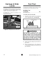
the carriage and cross slide have screws that can 
be  tightened  to  provide  additional  rigidity  during 
operation, especially during heavy cuts.

see

 figure 27  to  identify  the  locations  of  the 

locks for each device.

Carriage & Slide 

Locks

figure 27. Carriage and cross slide locks.

Cross slide

lock screw

Carriage

lock screw

Summary of Contents for G0745

Page 1: ... For models manufactured since 11 13 Copyright NOVEMBER 2013 By Grizzly Industrial Inc Warning No portion of this manual may be reproduced in any shape Or form without the written approval of Grizzly Industrial inc BLTSDM16121 printed IN CHINA V1 11 13 ...

Page 2: ...ng grinding tool integrity and the usage of personal protective equipment The manufacturer will not be held liable for injury or property damage from negligence improper training machine modifications or misuse Some dust created by power sanding sawing grinding drilling and other construction activities contains chemicals known to the State of California to cause cancer birth defects or other repr...

Page 3: ...21 Chuck Removal 21 Reversing Jaws 22 Scroll Chuck Clamping 23 Tailstock 24 Tailstock Quill Specs 24 Positioning Tailstock 24 Using Quill 24 Center 25 Mounting Center in Tailstock 25 Mounting Workpiece Between Centers 25 Carriage Slide Locks 26 Tool Post 26 Installing Tool 26 Aligning Cutting Tool with Spindle Centerline 27 Manual Feed 28 Spindle Speed 29 Determining Spindle Speed 29 Selecting Spi...

Page 4: ...e about it Where could it be improved Please take a few minutes to give us feedback Grizzly Documentation Manager P O Box 2069 Bellingham WA 98227 2069 Email manuals grizzly com Contact Info We are proud to provide a high quality owner s manual with your new machine We made every effort to be exact with the instruc tions specifications drawings and photographs contained inside sometimes we make mi...

Page 5: ...nter K Tailstock L Backsplash M Carriage Handwheel N Carriage O Cross Slide Handwheel P Rubber Foot Serious personal injury could occur if you connect the machine to power before completing the setup process DO NOT connect power until instructed to do so later in this manual Untrained lathe operators have an increased risk of becoming seriously injured Do not operate this machine until you have un...

Page 6: ...6 and the following descrip tions to become familiar with the basic controls of this lathe A Spindle Speed Dial Starts and stops spin dle rotation and controls spindle speed when rotated Rotate fully counterclockwise to turn OFF Rotate fully clockwise to maximize spindle speed B Fault Indicator Light Illuminates if chuck guard is opened during spindle rotation Close guard and turn spindle speed di...

Page 7: ...achine Your safety is VERY important to us at Grizzly Arbor A machine shaft that supports a cutting tool Backlash The amount of free play felt while changing rotation directions with the handwheels Cutting Speed The distance a point on a cutter moves in one minute expressed in meters or feet per minute Glossary of Terms Facing In lathe work cutting across the end of a workpiece usually to machine ...

Page 8: ... Cardboard Box Content Machine Weight 36 lbs Length x Width x Height 21 x 9 x 15 in Electrical Power Requirement 110V Single Phase 60 Hz Prewired Voltage 110V Full Load Current Rating 1 8A Minimum Circuit Size 15A Connection Type Cord Plug Power Cord Included Yes Power Cord Length 5 ft Power Cord Gauge 18 AWG Plug Included Yes Included Plug Type 5 15 Switch Type Variable Speed Dial Motors Main Typ...

Page 9: ... Quill Travel 7 8 in Tailstock Barrel Diameter 0 39 in Dimensions Bed Width 2 5 16 in Leadscrew Diameter 5 16 in Leadscrew TPI 18 TPI Leadscrew Length 12 in Construction Headstock Cast Iron Bed Hardened and Precision Ground Cast Iron Body Cast Iron Stand Formed Steel Paint Epoxy Other Specifications Country Of Origin China Warranty 1 Year Serial Number Location ID Label on Headstock ISO 9001 Facto...

Page 10: ...oof DANGEROuS ENvIRONMENTS do not use machinery in areas that are wet cluttered or have poor lighting operating machinery in these areas greatly increases the risk of accidents and injury MENTAL ALERTNESS REQuIRED Full mental alertness is required for safe operation of machin ery Never operate under the influence of drugs or alcohol when tired or when distracted for your Own Safety Read Instructio...

Page 11: ...educe accidental contact with moving parts or flying debris Make sure they are properly installed undamaged and working correctly fORCING MACHINERy do not force machine it will do the job safer and better at the rate for which it was designed NEvER STAND ON MACHINE serious injury may occur if machine is tipped or if the cutting tool is unintentionally contacted STAbLE MACHINE unexpected movement d...

Page 12: ...es Never exceed rate rpM of the chuck LONG STOCK SAfETy long stock can whip violently if not properly supported always support any stock that extends from the chuck headstock more than three times its own diameter CLEARING CHIpS Metal chips can be razor sharp avoid clearing them by hand or with a rag use a brush or vacuum instead SECuRE WORKpIECE an improperly secured workpiece can fly off spindle...

Page 13: ...ersized circuit to reduce the risk of these hazards avoid over loading the machine during operation and make sure it is connected to a power supply circuit that meets the specified circuit requirements for your own safety and protection of property consult an electrician if you are unsure about wiring practices or electrical codes in your area Note The circuit requirements listed in this man ual a...

Page 14: ... extension cord size gets longer and the gauge size gets smaller higher gauge numbers indicate smaller sizes Any extension cord used with this machine must contain a ground wire match the required plug and receptacle and meet the following require ments Minimum Gauge Size 18 AWG Maximum Length Shorter is Better 50 ft Grounding Plug Requirements Figure 7 Typical 5 15 plug and receptacle Grounding P...

Page 15: ...rier or its agent Otherwise filing a freight claim can be difficult When you are completely satisfied with the condi tion of your shipment inventory the contents Unpacking SUFFOCATION HAZARD Keep children and pets away from plastic bags or packing materials shipped with this machine Discard immediately The following are needed to complete the setup process but are not included with your machine De...

Page 16: ...fore beginning setup lay these items out and inventory them If any non proprietary parts are missing e g a nut or a washer we will gladly replace them or for the sake of expediency replacements can be obtained at your local hardware store Box 1 Figures 8 9 Qty A 3 Jaw Chuck 2 Pre installed 1 B Tool Post Pre installed 1 C Tailstock Pre installed 1 D Handwheel Handles 3 E Chuck Guard 1 F Spindle Key...

Page 17: ...c paint scraper optional basic steps for removing rust preventative 1 put on safety glasses 2 Coat the rust preventative with a liberal amount of cleaner degreaser then let it soak for 5 10 minutes 3 Wipe off the surfaces if your cleaner degreas er is effective the rust preventative will wipe off easily if you have a plastic paint scraper scrape off as much as you can first then wipe off the rest ...

Page 18: ...nt for safe operation and lon gevity of machine components For best results operate this machine in a dry environment that is free from excessive moisture hazardous chemi cals airborne abrasives or extreme conditions Extreme conditions for this type of machinery are generally those where the ambient temperature range exceeds 41 104 F the relative humidity range exceeds 20 95 non condensing or the ...

Page 19: ...g Power If you need to disconnect the machine from power for maintenance service or adjustments press the emergency stop button rotate the spindle speed dial fully counterclockwise and pull the plug completely out of the receptacle Once assembly is complete test run the machine to ensure it is properly connected to power and safety components function properly The test run consist of verifying the...

Page 20: ... before continuing operation Use the spindle speed dial to stop the machine disconnect it from power and call Tech Support for help 6 Reset the emergency stop button then lift the chuck guard all the way up Try restarting the spindle It should not start when the chuck guard is up If spindle rotation does start with the chuck guard open the chuck guard is not operating correctly This safety feature...

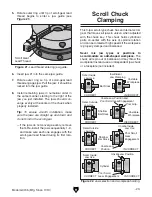
Page 21: ...dless of the content in this sec tion Grizzly Industrial will not be held liable for accidents caused by lack of training To reduce risk of eye injury from flying chips always wear safety glasses face shield when operating To complete a typical operation the operator does the following 1 Puts on safety glasses and a face shield ties back long hair rolls up long sleeves removes loose clothing jewel...

Page 22: ...ncentric workpieces straight turning between centers and boring Never use spindle speeds faster than the chuck RPM rating or the safe limits of your workpiece Excessive spindle speeds greatly increase the risk of the workpiece or chuck being thrown from the machine with deadly force Loose hair clothing or jewelry could get caught in machinery and cause serious personal injury Keep these items away...

Page 23: ...r and lightly oil all threads and mating surfaces 4 Thread the chuck onto the spindle nose and hand tighten it 5 Remove the cap screw that secures the end cover then open the end cover Figure 16 Spindle nose M14 1 0 threads Threads Spindle Shoulder 6 Insert the spindle key and chuck key as shown in Figure 17 and tighten the chuck snug against the spindle shoulder Figure 17 Tightening chuck onto sp...

Page 24: ...cess refer to Installation Removal Device on Page 20 3 Insert chuck keys into holes in chuck and outer ring see Figure 20 Hold chuck key stationary while turning outer ring counter clockwise then back jaws out and remove them 4 Use mineral spirits to clean debris and grime from jaws and chuck jaw guides When installing the jaws it is important to make sure they are installed correctly Incorrect in...

Page 25: ...ed and balanced Never mix jaw types or positions to accommodate an odd shaped workpiece The chuck will spin out of balance and may throw the workpiece Instead use an independent jaw chuck or a faceplate not included 6 Insert jaw 1 into the same jaw guide 7 Rotate outer ring so tip of scroll gear lead thread engages jaw Pull the jaw it should be locked into the jaw guide 8 Install remaining jaws in...

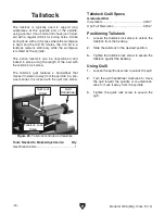
Page 26: ...ith the tailstock lock screw The tailstock quill features a handwheel that moves it toward or away from the spindle in a pre cise manner it is locked with the quill lock screw Figure 23 Tailstock controls and features Tailstock Lock Screw Quill Quill Lock Screw Quill Handwheel Tools Needed to Make Adjustments Qty Hex Wrench 5mm 1 Positioning Tailstock 1 Loosen the tailstock lock screw to unlock th...

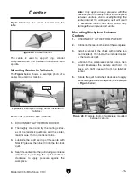
Page 27: ... it between the centers and hold it in place with light pressure from the tailstock center 5 Rotate the quill handwheel clockwise to apply pressure against the workpiece see example in Figure below Mounting Center in Tailstock The Figure below shows an example photo of a center mounted in a tailstock To mount a center in the tailstock 1 DISCONNECT LATHE FROM POWER 2 Thoroughly clean and dry the ma...

Page 28: ... cutting tool from the tool post will increase the risk of tool chatter breakage or tool loosening during operation which could cause metal pieces to be thrown at the operator or bystanders with great force DO NOT extend a cutting tool more than 2 5 times the width of its cross section e g 2 5 x 0 5 1 25 Figure 28 Example of tool mounted in tool post Cutting Tool Tool Post Screw The carriage and c...

Page 29: ...the surface of the cross slide to the tip of the center Adjust the cutting tool height so it is the same distance above the cross slide as the tailstock center Align the tip of the cutting tool with a tailstock center as instructed in the following proce dure To align the cutting tool with the tailstock center 1 Mount the cutting tool in the tool post then secure the post so the tool faces the tai...

Page 30: ...setting up and performing turning operations Cross Slide Handwheel Graduated Dial Increments 0 002 0 051mm One Full Revolution 0 056 1 42mm Use this handwheel to move the tool toward and away from the work The cross slide handwheel has an indirect read graduated dial This means the distance shown on the scale represents the actual distance the tool moves Figure 31 Manual handwheel controls Cross S...

Page 31: ...ial in order to produce the desired finish and optimize tool life Cutting Speed FPM x 12 Recommended Dia of Cut in inches x 3 14 Spindle Speed RPM Double if using carbide cutting tool Figure 32 Spindle speed formula for lathes Selecting Spindle Speed Twist the emergency stop button clockwise to reset it then rotate the spindle speed dial Figure 33 until the desired spindle speed is achieved Figure...

Page 32: ...block fin ish table top measures 1 x 13 x 23 and is 301 2 from the floor Bottom measures 21 x 32 700 lb Capacity T25206 11 Pc Carbide Bit Set 5 16 This 11 Pc Carbide Tipped Tool Bit Set includes a wide variety of tool types for just about any machining operation This set also includes two boring bars Boring bars measure 47 8 long Shank size for all is 5 16 T26622 Threaded Tailstock Chuck This tail...

Page 33: ...tton to prevent accidental startup Vacuum clean all chips and swarf from bed and slides Wipe down all unpainted or machined sur faces with an oiled rag Schedule To reduce risk of shock or accidental startup always disconnect machine from power before adjustments maintenance or service Cleaning Protecting Typically the easiest way to clean swarf from the machine is to use a wet dry shop vacuum that...

Page 34: ...lathe compo nents and will void the warranty Leadscrews Oil Type Grizzly SB1365 or ISO 68 Equivalent Oil Amount As Needed Lubrication Frequency Daily Before lubricating the longitudinal and cross slide leadscrews see Figure 37 clean them first with mineral spirits To access the longitudinal leadscrew remove the leadscrew cover which is attached with screws Use a stiff brush to help remove any debr...

Page 35: ...ce as necessary 5 Correct motor wiring connections Page 40 6 Replace fuse Page 37 7 Replace brushes Page 38 8 Test repair replace Motor is loud when cutting bogs down under load or overheats 1 Excessive depth of cut or feed rate 2 Spindle speed or feed rate wrong for cutting operation 3 Cutting tool is dull 1 Decrease depth of cut or feed rate 2 Refer to the feeds and speed charts in Machinery s H...

Page 36: ...lash setting see Page 35 5 Lubricate bedways Cutting tool or machine components vibrate excessively while cutting 1 Tool post not tight enough 2 Cutting tool sticks too far out of tool post lack of support 3 Gib out of adjustment 4 Dull cutting tool 5 Incorrect spindle speed or feed rate 1 Check for debris clean and retighten 2 Re install cutting tool so no more than 1 3 of the total length is sti...

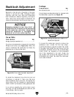
Page 37: ... backlash is adjusted by loosening Phillips head screw see Figure 38 When the screw is tightened the leadscrew nut draws the leadscrew up removing free play To adjust the backlash move the tool post out of the way or remove it Then rock the cross slide handwheel back and forth and tighten the screw slowly until the backlash is approximately 0 002 0 003 as indicated on the graduated dial If you end...

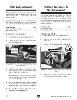
Page 38: ...osens the gib 4 When you are satisfied with the gib adjust ment keep the set screws from moving and re tighten the hex nuts to secure the settings 5 Re check the movement of the slide and if necessary repeat Steps 2 4 Figure 40 Cross slide gib adjustment hex nuts and set screws Cross Slide Adjustment Fasteners V Belt Tension Replacement The V belt stretches and wears with use An improperly tension...

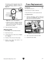
Page 39: ...nt Replacing V Belt 1 DISCONNECT LATHE FROM POWER 2 Open the end cover 3 Loosen the four cap screws shown in Figure 41 on Page 36 4 Carefully roll the V belt off of the pulleys 5 Install a new V belt then tension it as described on Page 36 Tool Needed Qty Flat Head Screwdriver 1 1 Replacement part number P0745125 If the spindle does not start replace the fuse To replace the fuse 1 Using the screwd...

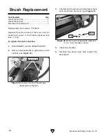
Page 40: ...ss than 1 4 long To replace the motor brushes 1 DISCONNECT LATHE FROM POWER 2 Remove the backsplash to gain acess to both brushes see Figure 44 Figure 44 Location of motor brush caps backsplash removed Brush Caps 4 Install new brushes 5 Re install the brush caps then replace the backsplash Figure 45 Motor brush components removed 1 of 2 motor brushes shown Cap Brush 3 Unscrew each brush cap and ca...

Page 41: ...nt at the time of printing but may not match your machine If you find this to be the case use the wiring diagram inside the motor junction box CAPACITORS INVERTERS Some capacitors and power inverters store an electrical charge for up to 10 minutes after being disconnected from the power source To reduce the risk of being shocked wait at least this long before working on capacitors EXPERIENCING DIF...

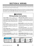
Page 42: ... PAGE 39 Control Panel Wiring Fault Power Emergency Stop Variable Speed Control Panel Backside View To Circuit Board Fuse Limit Switch N N L L SE4TB5 5A250V 4 4 250VAC BF021 K4 K3 WH24 2 Z4K7 JHK16 822 K1 K2 SE4TB5 5A250V K3 K4 Figure 46 Control panel wiring ...

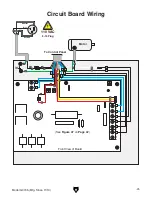
Page 43: ...fg Since 11 13 41 Circuit Board Wiring L1 GAN L2 A A K1 K2 Front View of Board L1 L2 A A A A K1 K2 To Control Panel Gnd Gnd Neutral Hot Ground 110 VAC 5 15 Plug L1 L2 K1 K2 Motor K3 K3 K4 K4 See Figure 47 on Page 42 ...

Page 44: ... 42 Model G0745 Mfg Since 11 13 Figure 47 Circuit board ...

Page 45: ...M6 1 X 14 20 P0745020 PHLP HD SCR M4 7 X 10 4 P0745004 LEADSCREW COVER 21 P0745021 LONGITUDINAL LEADSCREW 6 P0745006 TAP SCREW M2 9 X 6 5 22 P0745022 LEADSCREW SUPPORT RH 7 P0745007 TAP SCREW M3 X 8 23 P0745023 HANDWHEEL 8 P0745008 CIRCUIT BOARD XMT1115 24 P0745024 ACORN NUT M5 8 9 P0745009 CIRCUIT BOARD BACK PLATE 25 P0745025 HANDWHEEL HANDLE 10 P0745010 CAP SCREW M6 1 X 12 26 P0745026 HANDLE STE...

Page 46: ...M4 7 X 8 67 P0745067 FUSE HOLDER 37 P0745037 EXT RETAINING RING 17MM 68 P0745068 FLEXIBLE CORD ASS7 13 X 270MM 38 P0745038 SPINDLE PULLEY 69 P0745069 FLAT HD SCR M4 7 X 8 39 P0745039 SPACER 70 P0745070 CHUCK GUARD 40 P0745040 SPACER 71 P0745071 CHUCK GUARD PIVOT SHAFT 41 P0745041 HEADSTOCK 72 P0745072 KEY 3 X 3 X 6 42 P0745042 PULLEY COVER 73 P0745073 SPACER 43 P0745043 HEX NUT M4 7 74 P0745074 CO...

Page 47: ...P HD SCR M4 7 X 6 120 P0745120 CAP SCREW M4 7 X 14 81 P0745081 CAP SCREW M6 1 X 35 121 P0745121 CROSS LEADSCREW BRACKET 82 P0745082 QUILL 122 P0745122 CARRIAGE GIB PLATE 83 P0745083 CAP SCREW M6 1 X 16 123 P0745123 SET SCREW M4 7 X 6 84 P0745084 SET SCREW M6 1 X 8 DOG PT 126 P0745126 CHUCK KEY 5MM 85 P0745085 SET SCREW M6 1 X 8 127 P0745127 SPINDLE KEY 5MM 86 P0745086 TAILSTOCK LEADSCREW 128 P0745...

Page 48: ...P0745207 MACHINE ID LABEL 203 P0745203 CONTROL PANEL LABEL 208 P0745208 GRIZZLY COM LABEL 204 P0745204 SAFETY GLASSES LABEL 209 P0745209 ELECTRICITY LABEL 205 P0745205 READ MANUAL LABEL Safety labels help reduce the risk of serious injury caused by machine hazards If any label comes off or becomes unreadable the owner of this machine MUST replace it in the original location before resuming operati...

Page 49: ... metalworker ____ 0 2 Years ____ 2 8 Years ____ 8 20 Years ____20 Years 6 How many of your machines or tools are Grizzly ____ 0 2 ____ 3 5 ____ 6 9 ____10 7 Do you think your machine represents a good value _____Yes _____No 8 Would you recommend Grizzly Industrial to a friend _____Yes _____No 9 Would you allow us to use your name as a reference for Grizzly customers in your area Note We never use ...

Page 50: ...D LINE FOLD ALONG DOTTED LINE GRIZZLY INDUSTRIAL INC P O BOX 2069 BELLINGHAM WA 98227 2069 Place Stamp Here Name_______________________________ Street_______________________________ City______________State______Zip______ Send a Grizzly Catalog to a friend ...

Page 51: ... shall be tried in the State of Washington County of Whatcom We shall in no event be liable for death injuries to persons or property or for incidental contingent special or consequential damages arising from the use of our products To take advantage of this warranty contact us by mail or phone and give us all the details We will then issue you a Return Number which must be clearly posted on the o...

Page 52: ......

Reviews: