background image

Model G0686 (Mfd. Since 01/15)

-23-

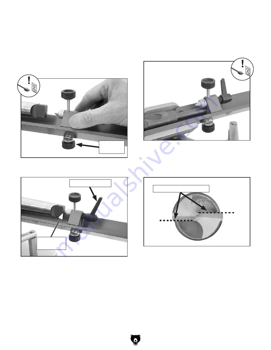
8.  Position  and  secure  the  tailstock  up  against 

the back of the bit so that it will not move away 
from the grinding wheel during operation.

— 

If the bit shank is center-drilled: Insert 
the tailstock center point into the bit shank  
center-drilled hole, then tighten the tailstock 
bottom  lock  knob  and  height  lock  lever  to 
secure the setting (see 

Figures 21–22).

Figure 21. Aligning the tailstock with the center-

drilled hole of the bit shank.

Bottom 

Lock Knob

Figure 22. Tailstock in the correct position 

against the center-drilled shank.

Tailstock

Center Point

Height Lock Lever

9.  Rotate  the  bit  so  that  the  cutting  edges  are 

horizontal, as shown in 

Figure 24.

— 

If the bit shank is not center-drilled: 
Raise the tailstock center point above the 
bit shank and lock it in place. Then, move 
the tailstock base up against the bit shank 
and tighten the bottom lock knob to hold it 
in place, as shown in 

Figure 23.

Figure 23. Tailstock in proper position against a 

bit shank that is not center-drilled.

Figure 24. Bit rotated so that the cutting edges 

are horizontal.

Cutting Edges Horizontal

Summary of Contents for G0686

Page 1: ...dels manufactured since 01 15 COPYRIGHT MAY 2009 BY GRIZZLY INDUSTRIAL INC REVISED MARCH 2019 MN WARNING NO PORTION OF THIS MANUAL MAY BE REPRODUCED IN ANY SHAPE OR FORM WITHOUT THE WRITTEN APPROVAL OF GRIZZLY INDUSTRIAL INC TS11442 PRINTED IN TAIWAN V2 03 19 ...

Page 2: ...ng grinding tool integrity and the usage of personal protective equipment The manufacturer will not be held liable for injury or property damage from negligence improper training machine modifications or misuse Some dust created by power sanding sawing grinding drilling and other construction activities contains chemicals known to the State of California to cause cancer birth defects or other repr...

Page 3: ...tions 15 Assembly 16 Test Run 17 SECTION 4 OPERATIONS 18 Grinding Tips 18 Drill Bit Terminology 19 Wheel Care 19 Wheel Inspection 20 Grinding Wheels 21 Grinding Cutting Edge Point Angle 22 SECTION 5 ACCESSORIES 27 SECTION 6 MAINTENANCE 28 Schedule 28 Cleaning Protecting 28 Wheel Dressing 28 Wheel Storage 28 Replacing Light Bulb 28 Lubrication 29 SECTION 7 SERVICE 30 Troubleshooting 30 Motor Brushe...

Page 4: ...ntact Info We are proud to provide a high quality owner s manual with your new machine We made every effort to be exact with the instruc tions specifications drawings and photographs in this manual Sometimes we make mistakes but our policy of continuous improvement also means that sometimes the machine you receive is slightly different than shown in the manual If you find this to be the case and t...

Page 5: ...ard Grinding Wheel Work Lamp Switch Motor ON OFF Switch Carriage Handwheel Carriage Pivot Handle Stop Rod 1 of 2 Pivot Base The tailstock bit carrier and jig base are components of the jig assembly Tailstock Bit Carrier Jig Base To reduce your risk of serious injury read this entire manual BEFORE using machine ...

Page 6: ... cut Bit Carrier Keeps the bit steady with a V type trough configuration With the use of the pivot lever the pivot base moves the drill bit in a precise path across the cutting edge of the grinding wheel The jig assembly and pivot base are mounted on the carriage which is moved toward or away from the wheel with the use of the handwheel Refer to Figure 3 and the following descriptions to become fa...

Page 7: ...110V Single Phase 60 Hz Full Load Current Rating 4 5A Minimum Circuit Size 15A Connection Type Cord Plug Power Cord Included Yes Power Cord Length 5 ft Power Cord Gauge 16 AWG Plug Included Yes Included Plug Type 5 15 Switch Type ON OFF Rocker Motor Main Horsepower 1 2 HP Phase Single Phase Amps 4 5A Speed 6800 RPM Type DC Universal Number Of Speeds 1 Power Transfer Direct Drive Bearings Shielded ...

Page 8: ...n Warranty 1 Year Approximate Assembly Setup Time 30 min Serial Number Location Machine ID Label ISO 9001 Factory No Certified by a Nationally Recognized Testing Laboratory NRTL No Features Title Case Spiral Point Grinding Capability Prism Clamp for Drill Grinding Calibrated Infeed Handwheel 2 Axis Adjustable Center 16 Drill Tray LED Work Light ...

Page 9: ...d proof DANGEROUS ENVIRONMENTS Do not use machinery in areas that are wet cluttered or have poor lighting Operating machinery in these areas greatly increases the risk of accidents and injury MENTAL ALERTNESS REQUIRED Full mental alertness is required for safe operation of machin ery Never operate under the influence of drugs or alcohol when tired or when distracted For Your Own Safety Read Instru...

Page 10: ... moving parts or flying debris Make sure they are properly installed undamaged and working correctly BEFORE operating machine FORCING MACHINERY Do not force machine It will do the job safer and better at the rate for which it was designed NEVER STAND ON MACHINE Serious injury may occur if machine is tipped or if the cutting tool is unintentionally contacted STABLE MACHINE Unexpected movement dur i...

Page 11: ...rating a Drill Bit Grinder are as follows You can be blinded or killed by flying debris created by a chipped or damaged grinding wheel Your fingers can be cut or amputated by the rotating grinding wheel You can also suffer crushing injuries from getting hair loose clothing or jewelry entangled in the wheel To reduce your risk of serious injury when operating this machine completely heed and unders...

Page 12: ...ersized circuit To reduce the risk of these hazards avoid over loading the machine during operation and make sure it is connected to a power supply circuit that meets the specified circuit requirements For your own safety and protection of property consult an electrician if you are unsure about wiring practices or electrical codes in your area Note Circuit requirements in this manual apply to a de...

Page 13: ...ord size gets longer and the gauge size gets smaller higher gauge numbers indicate smaller sizes Any extension cord used with this machine must be in good condition and contain a ground wire and matching plug receptacle Additionally it must meet the following size requirements Minimum Gauge Size 14 AWG Maximum Length Shorter is Better 50 ft Grounding Plug Requirements Figure 4 Typical 5 15 plug an...

Page 14: ...ave resolved any issues between Grizzly or the shipping agent You MUST have the original pack aging to file a freight claim It is also extremely helpful if you need to return your machine later Unpacking The following is a list of items shipped with your machine Before beginning setup lay these items out and inventory them If any non proprietary parts are missing e g a nut or a washer we will glad...

Page 15: ...Model G0686 Mfd Since 01 15 13 Hardware Recognition Chart USE THIS CHART TO MATCH UP HARDWARE DURING THE INVENTORY AND ASSEMBLY PROCESS 5mm 5mm Flat Head Cap Screw ...

Page 16: ...es Before cleaning gather the following Disposable rags Cleaner degreaser WD 40 works well Safety glasses disposable gloves Plastic paint scraper optional Basic steps for removing rust preventative 1 Put on safety glasses 2 Coat the rust preventative with a liberal amount of cleaner degreaser then let it soak for 5 10 minutes 3 Wipe off the surfaces If your cleaner degreas er is effective the rust...

Page 17: ...ronment The physical environment where the machine is operated is important for safe operation and lon gevity of machine components For best results operate this machine in a dry environment that is free from excessive moisture hazardous chemi cals airborne abrasives or extreme conditions Extreme conditions for this type of machinery are generally those where the ambient temperature range exceeds ...

Page 18: ... Positioning Pin Pivot Base Jig Base Assembly Tools Needed Not Included Qty Hex Wrench 5mm 1 To assemble the grinder 1 Use the provided cap screw to install the handle onto the handwheel as shown in Figure 7 2 Remove the jig mounting hex bolt and flat washer shown in Figure 8 from the pivot base Figure 7 Handle installed onto the handwheel Handle The machine must be fully assembled before it can b...

Page 19: ...ration or rubbing noises Strange or unusual noises should be inves tigated and corrected before operating the machine further Always disconnect the machine from power when investigating or correcting potential problems 5 Turn the machine OFF The Test Run consists of verifying the following 1 The motor powers up and runs correctly Once assembly is complete test run the machine to ensure it is prope...

Page 20: ... for the diameter of the drill bit When setting up the bit in the jig make sure there is a safe clearance of at least 1 4 between the bit and the wheel when the bit has reached the end of its inward path refer to Selecting Correct Grinding Wheel on the previous page for additional information Use a steady motion with the pivot lever as you move the bit across the cutting edge of the wheel An overl...

Page 21: ...he operator and others in the area Here are some tips to help you avoid breaking the wheel Always transport store and handle wheels with care Wheels may be damaged if they are dropped or if heavy objects are stacked on them Only use wheels that are rated for the RPM of the grinder Mount the wheel properly see Changing Grinding Wheel on Page 21 Do not push the bit into the grinding wheel with such ...

Page 22: ...ated RPM of this wheel WARNING Grinding can be dangerous Visually inspect this wheel for cracks nicks chips Type 1 Aluminum Oxide 60 Grit Grade L Vitrified Bond 4 An undamaged wheel will emit a clear metal lic ring or ping sound in each of these spots A damaged wheel will respond with a dull thud that has no clear tone 5 If you determine from the ring test that the wheel is damaged DO NOT use it T...

Page 23: ... on the left hand side of the motor arbor to keep it from turning then rotate the grinding wheel counterclockwise to remove it from the arbor as shown in Figure 17 3 Store the grinding wheel in a safe dry loca tion that is not exposed to extreme tempera tures 4 Visually check the replacement wheel for cracks soft spots excessive wear or any other damage if you are not sure about the condition of t...

Page 24: ...4 Loosen the height lock lever see Figure 18 Figure 18 Bit carrier height scale and height lock lever Bottom of Bit Carrier Scale Height Lock Lever 5 Adjust the height set screw to raise or lower the bit carrier until the bottom of the carrier base is even with the number on the height scale that is equal to the bit s diameter see Figures 18 19 The height scale is in millimeters 6 Tighten the heig...

Page 25: ...of the bit shank Bottom Lock Knob Figure 22 Tailstock in the correct position against the center drilled shank Tailstock Center Point Height Lock Lever 9 Rotate the bit so that the cutting edges are horizontal as shown in Figure 24 If the bit shank is not center drilled Raise the tailstock center point above the bit shank and lock it in place Then move the tailstock base up against the bit shank a...

Page 26: ...the operator s hands could be drawn into the wheel To reduce the risk of personal injury and property damage ALWAYS make sure the drill bit is properly secured with the tailstock and flute pin before operation 11 Rotate the jig assembly until the rotational scale reads the desired angle of cut at the mark then tighten the hex bolt at the base to secure the setting see Figure 27 Note The example sh...

Page 27: ...edge of the wheel 1 4 Safe Clearance 14 While holding the drill bit to keep it from mov ing carefully push the stop rod in until you feel resistance then tighten the lock knob to secure the setting Note When the stop rod is locked in the cor rect position it will limit the travel of the bit so that it will not reach the opposite wheel lip 15 Recheck the position of the drill bit in the jig Make su...

Page 28: ...nect the machine to power turn it ON and wait for the wheel to reach full speed 19 Hold the drill bit firmly against the tailstock and flute pin with your right hand 20 To perform a grinding pass move the pivot lever with a moderate and steady motion to pass the bit across the wheel s inside cutting edge then stop when you feel resistance from the front stop rod 21 Without moving your right hand r...

Page 29: ...this machine by Grizzly NOTICE Refer to our website or latest catalog for additional recommended accessories order online at www grizzly com or call 1 800 523 4777 Figure 33 Assorted eye protection Basic Eye Protection T20501 Face Shield Crown Protector 4 T20502 Face Shield Crown Protector 7 T20503 Face Shield Window T20451 Kirova Clear Safety Glasses T20452 Kirova Anti Reflective S Glasses T20456...

Page 30: ...ew and slides Check grinding wheel for loading up Schedule To reduce risk of shock or accidental startup always disconnect machine from power before adjustments maintenance or service Cleaning Protecting Cleaning the Model G0686 is relatively easy Vacuum excess debris and wipe off the remaining dust with a dry cloth Grinding wheels can be easily damaged so it is important to store them properly Fo...

Page 31: ...adscrew Slides Remove the front panels of the pivot base and car riage to access the slides and carriage leadscrew see Figure 37 then use a shop rag clean brush and mineral spirits to clean away the grease and grime from the slides and leadscrew Apply a small amount of multi purpose grease to the slides and leadscrew then move the devices through their full range of motion to distribute the lubric...

Page 32: ...otor bearings at fault 6 Motor shaft bent 1 Inspect replace damaged bolts nuts and re tighten with thread locking fluid 2 Dress replace grinding wheel 3 Adjust feet shim or tighten mounting hardware 4 Properly mount the bit in the jig assembly hold firmly during operation 5 Test by rotating shaft rotational grinding loose shaft requires bearing replacement 6 Test with dial indicator and replace mo...

Page 33: ...move the front motor brush assembly as shown in Figure 38 Note As you remove the brush assembly make note of the orientation of the carbon tip so that if it is still good you can re install it the same way 3 Measure the length of the carbon tip If the carbon tip is worn down to 1 4 6mm or less replace both brush assemblies with new ones Note Replacement motor brushes are avail able through Grizzly...

Page 34: ...nt at the time of printing but may not match your machine If you find this to be the case use the wiring diagram inside the motor junction box CAPACITORS INVERTERS Some capacitors and power inverters store an electrical charge for up to 10 minutes after being disconnected from the power source To reduce the risk of being shocked wait at least this long before working on capacitors EXPERIENCING DIF...

Page 35: ...86 Mfd Since 01 15 33 READ ELECTRICAL SAFETY ON PAGE 32 Motor ON OFF Switch Lamp Switch Lamp 4 1 2 5 6A05 GW Diodes Neutral Hot Ground 110 VAC 5 15 Plug wiring diagram Wiring Diagram Figure 39 Model G0686 wiring ...

Page 36: ...CH 16A 250V 3 P0686003 LAMP LENS 11 P0686011 LAMP SWITCH 12V 240V 4 P0686004 LENS RUBBER SEAL 12 P0686012 POWER CORD 16G 3W 73 5 15P 5 P0686005 RUBBER FOOT 13 P0686013 PHLP HD SCR M3 5 X 10 6 P0686006 HEX BOLT M8 1 25 X 20 14 P0686014 STRAIN RELIEF TYPE 6 5 8 ST 7 P0686007 ACRYLIC COVER SECTION 9 PARTS We do our best to stock replacement parts when possible but we cannot guarantee that all parts s...

Page 37: ... DESCRIPTION REF PART DESCRIPTION 15 P0686015 GRINDING WHEEL 60G 60OD X 35MMID 21 P0686021 PHLP HD SCR M5 8 X 10 17 P0686017 GRINDING WHEEL 60G 70OD X 54MMID 22 P0686022 FAN COVER 18 P0686018 ARBOR SPACER 23 P0686023 MOTOR BRUSH HOUSING 19 P0686019 WHEEL GUARD 24 P0686024 MOTOR BRUSH 20 P0686020 BUTTON HD CAP SCR M5 8 X 12 25 P0686025 MOTOR BRUSH CAP ...

Page 38: ...PIN 5 X 12 28 P0686028 FLAT HD SCR M5 8 X 8 38 P0686038 FLAT WASHER 10MM 29 P0686029 THREADED LOCK SHAFT 39 P0686039 HEX BOLT M10 1 5 X 30 30 P0686030 KNURLED KNOB M6 1 X 32 40 P0686040 SLOTTED V BLOCK 31 P0686031 SLIDE BLOCK 41 P0686041 KNURLED KNOB M4 7 32 P0686032 FLAT WASHER 6MM 42 P0686042 HEX NUT M4 7 33 P0686033 LOCK LEVER M6 1 X 12 43 P0686043 SPECIAL SET SCREW M4 7 X 32 34 P0686034 LOCK L...

Page 39: ... P0686061 CARRIAGE 49 P0686049 COPPER PIN 62 P0686062 PLUG 50 P0686050 REAR STOP ROD 63 P0686063 UPPER CONNECTING BLOCK 51 P0686051 CAP SCREW M6 1 X 20 64 P0686064 LOWER CONNECTING BLOCK 52 P0686052 KNOB 1 2 20 65 P0686065 HANDWHEEL 53 P0686053 CAP SCREW M10 1 5 X 25 66 P0686066 HANDLE 54 P0686054 KNURLED KNOB M6 1 X 30 67 P0686067 SPECIAL SCREW M6 1 X 55 55 P0686055 SPECIAL SCREW M10 1 5 X 25 68 ...

Page 40: ...ECT POWER LABEL 72 P0686072 WHEEL ROTATION LABEL 76 P0686076 READ MANUAL LABEL 73 P0686073 GRIZZLY PUTTY TOUCH UP PAINT 77 P0686077 GRIZZLY LOGO 74 P0686074 EYE LUNG HAZARD LABEL Safety labels help reduce the risk of serious injury caused by machine hazards If any label comes off or becomes unreadable the owner of this machine MUST replace it in the original location before resuming operations For...

Page 41: ......

Page 42: ...D LINE FOLD ALONG DOTTED LINE GRIZZLY INDUSTRIAL INC P O BOX 2069 BELLINGHAM WA 98227 2069 Place Stamp Here Name_______________________________ Street_______________________________ City______________State______Zip______ Send a Grizzly Catalog to a friend ...

Page 43: ...for death injuries to persons or property or for incidental contingent special or consequential damages arising from the use of our products To register the warranty scan the QR code below You will be directed to the Warranty Registration page on Grizzly com Enter all applicable information for the product To take advantage of this warranty contact us by mail or phone and give us all the details W...

Page 44: ...REVISED ...

Reviews: